


www.ezurio.com
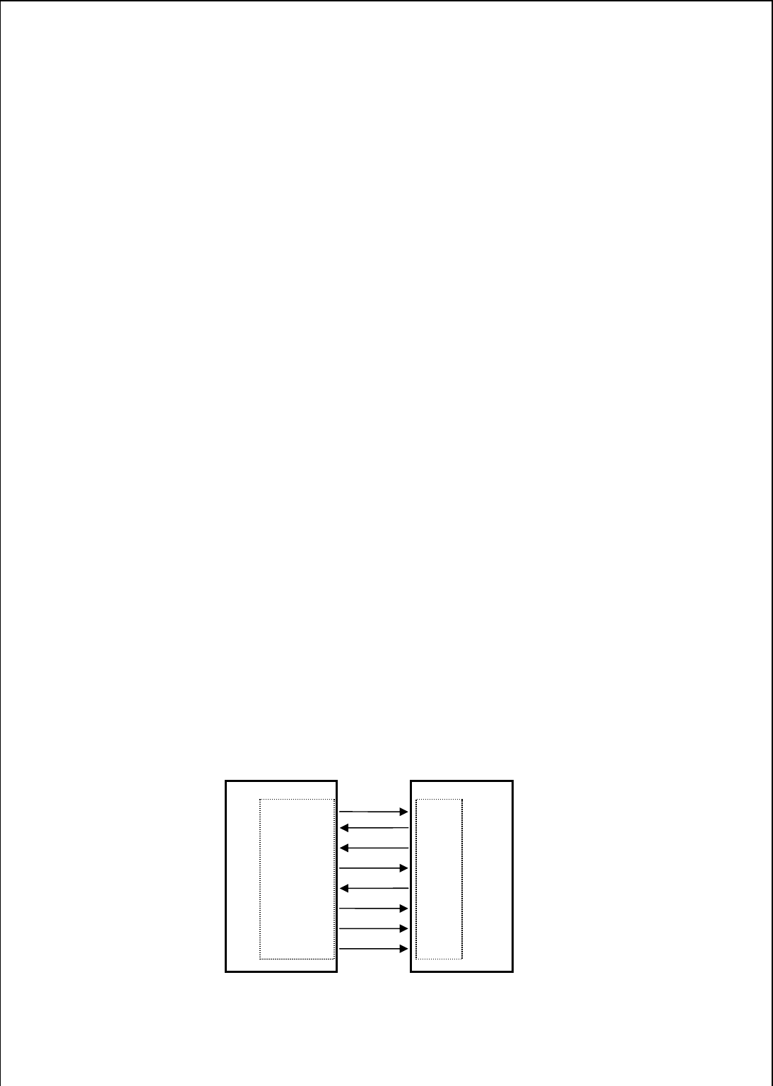
Serial Module
UART Interface
UART_TX
UART_RX
UART_CTS
UART_RTS
UART_DSR
UART_DTR
UART_RI
UART_DCD
/RXD
/TXD
/RTS
/CTS
/DTR
/DSR
/RING
/DCD
RS232 Interface
6. Functional Description
The BISM2 Bluetooth module is a self-contained Bluetooth product and requires only power to
implement full Bluetooth communication. The integrated, high performance antenna together with the
RF and Base-band circuitry provides the Bluetooth wireless link and the UART interface provides a
connection to the host system.
The variety of interfaces and the AT command set allow the BISM2 module to be used for a wide
number of short range wireless applications, from simple cable replacement to complex multipoint
applications, where multiple radio links are active at the same time.
The complexity and flexibility of configuration are made simple for the design engineer by the
integration of a extremely comprehensive set of AT commands, supplemented with a range of “S”
registers which are used for non-volatile storage of system parameters. These are fully documented
in the “Blu2i AT Command Reference Manual”.
To provide the widest scope for integration a range of different physical host interfaces are provided:
6.1 Interfaces
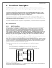
6.1.1 UART interface
UART_TX, UART_RX, UART_RTS and UART_CTS form a conventional asynchronous serial data port
with handshaking. The interface is designed to operate correctly when connected to other UART
devices such as the 16550A. The signalling levels are nominal 0V and 3.3V and are inverted with
respect to the signalling on an RS232 cable. The interface is programmable over a variety of bit
rates; no, even or odd parity; stop bit and hardware flow control. The default condition on power-up
is pre-assigned in the external Flash. Two-way hardware flow control is implemented by UART_RTS
and UART_CTS. UART_RTS is an output and is active low. UART_CTS is an input and is active low.
These signals operate according to normal industry convention.
By writing different values to the relevant S register the UART_RI can be continuously polled to detect
incoming communication. The UART_RI signal serves to indicate incoming calls.
UART_DSR is an active low input. It should be connected to DTR output of the host. When the module
is running in high speed mode (See definition for S Reg 507), this pin should be asserted by the host
to ensure connection is maintained. A de-assertion is taken to mean that the connection should be
dropped, or an online command mode is being requested.
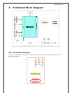
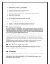
The module communicates with the customer application using the following signals:
RS-232
Port /TXD @ application sends data to the module’s UART_RX signal line
Port /RXD @ application receives data from the module’s UART_TX signal line
Figure 6.1 : UART interfaces
Note that the serial module output is at 3.3V CMOS logic levels. Level conversion must be added to
interface with an RS-232 level compliant interface.
Application