


www.ezurio.com
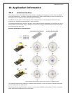
9. Application Examples
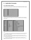
9.1 RS232 Modem Signals
Just as a telephony modem has control and status lines, the blu2i Module also provides for 6 control
and status lines as per the table below. The direction column is as seen from the module’s viewpoint.
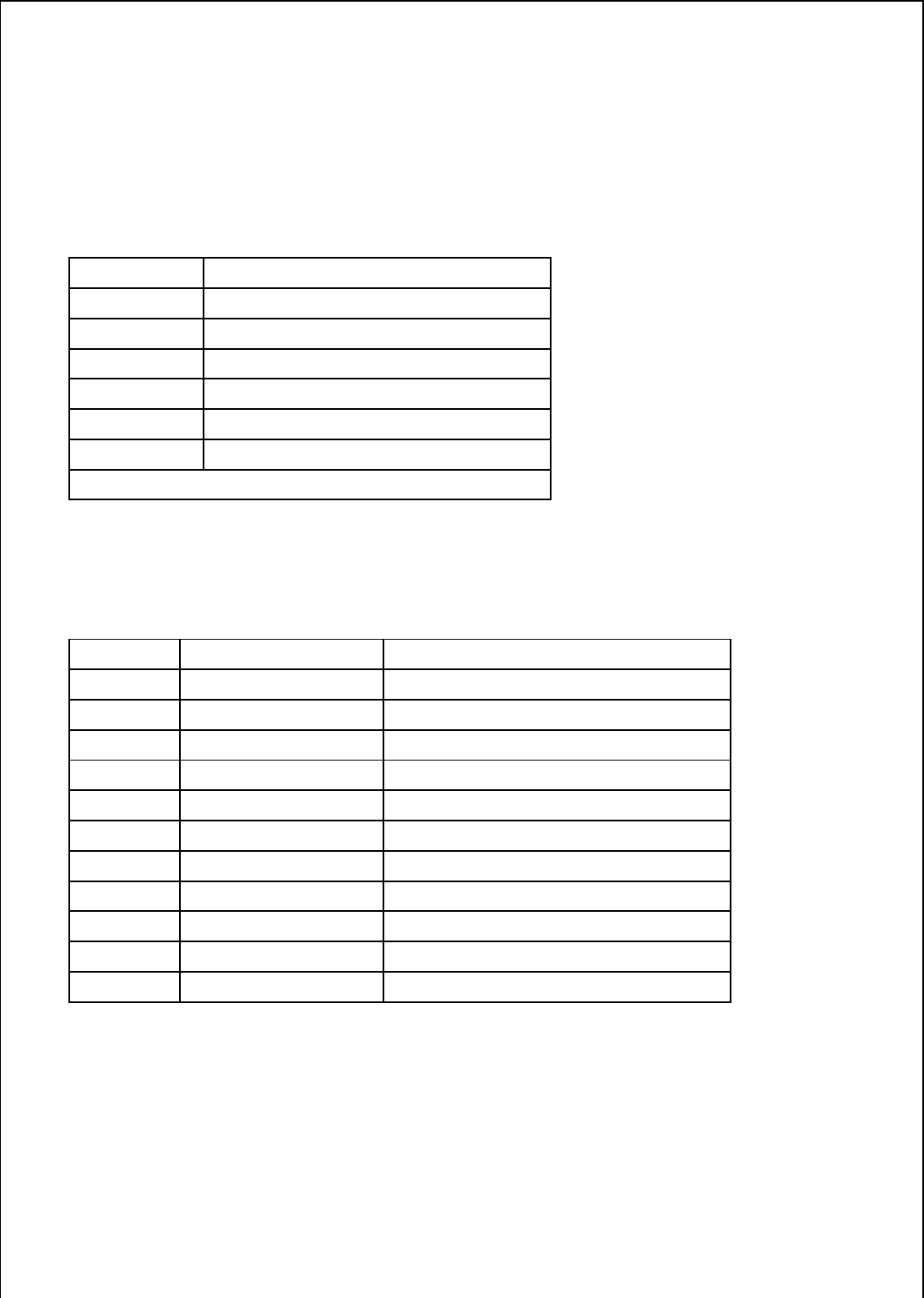
Direction Function
IN or OUT * CI also known as RI (Ring Indicate)
IN or OUT * DCD (Data Carrier Detect)
IN DSR (Data Set ready)
OUT DTR (Data Terminal Ready)
IN CTS (Clear to Send)
OUT RTS (Request to Send)
* configurable with S register 552
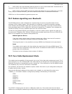
The first four lines are under program control. These use four of the GPIO pins and are mapped to
I/O as per the table below. The last two are under control of the UART driver and their functionality is
always enabled.
Direction Connector Pin Label Function
IN/OUT GPIO1 General Purpose I/O
IN/OUT GPIO2 General Purpose I/O
IN/OUT UART_RI Input/Output from module
IN/OUT UART_DCD Input/Output from module
IN UART_DSR Input to Module
IN/OUT GPIO3/UART_DTR General Purpose I/O (or DTR functionality)
IN/OUT GPIO4/LED General Purpose I/O (LED)
IN/OUT GPIO5 General Purpose I/O
IN/OUT GPIO6 General Purpose I/O
IN/OUT GPIO7 General Purpose I/O
IN/OUT GPIO8 General Purpose I/O
Notes:
1. PIO4 (DSR) is used by the blu2i module to sense that the host is connected, and is intricately
linked with connections. For outgoing calls, if this line is not asserted then an error is indicated.
Similarly for AT+BTP and AT+BTG.
While in a call, for appropriate modes, a de-assertion means fall into command state. If the de-
assertion exists for longer than the period specified in S Register 519 then the connection is dropped
as if an ATH command was received.
2. PIO2 (RI), is normally de-asserted. When an incoming connection is detected it will be
asserted, until the connection is either answered or rejected using ATA and ATH respectively. See S
Registers 552 & 553 for more details