


www.ezurio.com
10.2 Power Supply Considerations
The power supply for the Module has to be a single voltage source of Vcc within the range of 3.6 V to
7.0 V. It must be able to provide sufficient current in a transmit burst. This can rise to 65mA.
The Module includes regulators to provide local 3.3V. This rail is accessible on connector J2 for
monitoring purposes only. Under no circumstances should this pin be used to source current.
Power (Vcc) can be provided via the board-to-board connector Pin 29 on J2.
10.3 Power-On-Reset (Power Cycling and Brown Out
considerations).
The Module is provided with an active high reset pin (Hirose 40way DF12C connector pin 13). Upon
the application of power, the Power On Reset circuit built into the Module will ensure that the unit
starts correctly. There is no need for an external power reset monitor.
Note: The previous version of the Bluetooth Serial Module required an external Brown Out circuit to
ensure correct operation. This circuitry has now been incorporated into the module. The power
supply has been designed to work with previous versions of customer circuitry that may or may not
have external brown-out implementations. Customers migrating from a BISM1 to BISM2 module may
be able to simplify their power supply circuitry as a result..
10.4 RF Shield
To meet FCC requirements, all modules are supplied with a soldered RF shield. This meets the
requirement that users may not be able to access RF circuitry without special tools. Removal of the
shield may negate RF approvals.
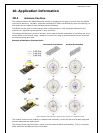
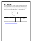
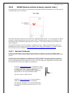
10.5 Mounting the Module onto the application platform
There are many ways to properly install the Module in the host device. An efficient approach is to
mount the PCB to a frame, plate, rack or chassis. Fasteners can be M1.8 or M2 screws plus suitable
washers, circuit board spacers, or customized screws, clamps, or brackets in 2.2mm diameter holes.
Note that care should be taken to ensure the head of the fixing does not interfere with the circuit.
Nylon fixings are recommended. In addition, the board-to-board connection can also be utilized to
achieve better support.
The antenna (Brown square component on top side of PCB) must not be influenced by any other
PCBs, components or by the housing of the host device. The proximity of the antenna to large
metallic objects can affect the range and performance of the system. Designers should carefully
consider the location of the Module and the type of enclosure material that is used.
To prevent mechanical damage, be careful not to force, bend or twist the Module. Be sure it is
positioned flat against the host device.