


www.ezurio.com
3. PIO3 (DCD) will be de-asserted when the device is in the unconnected state. Asserted when a
connection is active. See S Registers 552 and 553 for more details.
4. PIO5 is either used as GPIO or driven as UART_DTR. When the unit is configured in pure host
mode, this pin is forced into UART_DTR and is asserted when there is a Bluetooth connection.
GPIO Pins 1 to 8 are available for general purpose use.
9.2 Modem signalling over Bluetooth
The RFCOMM protocol used in Bluetooth for implementing the serial port profile allows for the
exchange of four modem signals. This information is contained in a special transparent message
which contains bits identified as RTR, RTC, DV and IC which depending on the type of serial device
being emulated maps to DTR or DSR, RTS, DCD and RI respectively. In addition, this message also
includes the ability to convey a BREAK input from one end to the other.
To allow for the greatest flexibility and variability in how the modem control signals are used out in
the real world, S Registers 551, 552 and 553 have been provided which allow for any of RTR,RTC,DV
and IC to be mapped to any modem control/status line.
BREAK signal on RX line
If the host sends a break signal of duration greater than 100ms, then the blu2i module is
configured to treat that as a signal to perform a hardware reset.
This being the case it is not possible to convey a BREAK over Bluetooth to the peer device.
Reset
The module can be reset by the host without the need of any I/O using a BREAK signal. The
module has been configured to reset when the RX line detects a break condition for durations
greater than 100 milliseconds.
The Reset line has a fixed pull down resistor of 10kOhm
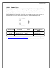
9.3 Pure Cable Replacement Mode
The module has the capability of being preset into a pure 5-wire data cable replacement mode. The 5
wires being RX, TX, CTS, RTS and GND. This mode requires no changes to a host application since the
Bluetooth connection is automatically set up on power up. If the connection is lost the BISM2 module
will constantly retry until the connection is reinstated.
By implication, two devices are needed to replace a cable. One device is pre-configured to always be
a master and the other, a slave.
Assuming the Bluetooth address of the master to be <bdaddr_m> and that of the slave to be
<bdaddr_s>, the master module is configured by sending it the following AT commands:
AT&F*
ATS512=1
ATS504=1
ATS507=2
ATS530=2000
AT&W
AT+BTR<bdaddr_s>
The ATS507=2 setting puts the device in DSR drop mode only. This means that when the device
needs to be reconfigured, deasserting the DSR line will ensure that the module responds quickly to AT