


www.ezurio.com
3.2 Pin Descriptions
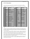
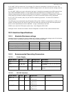
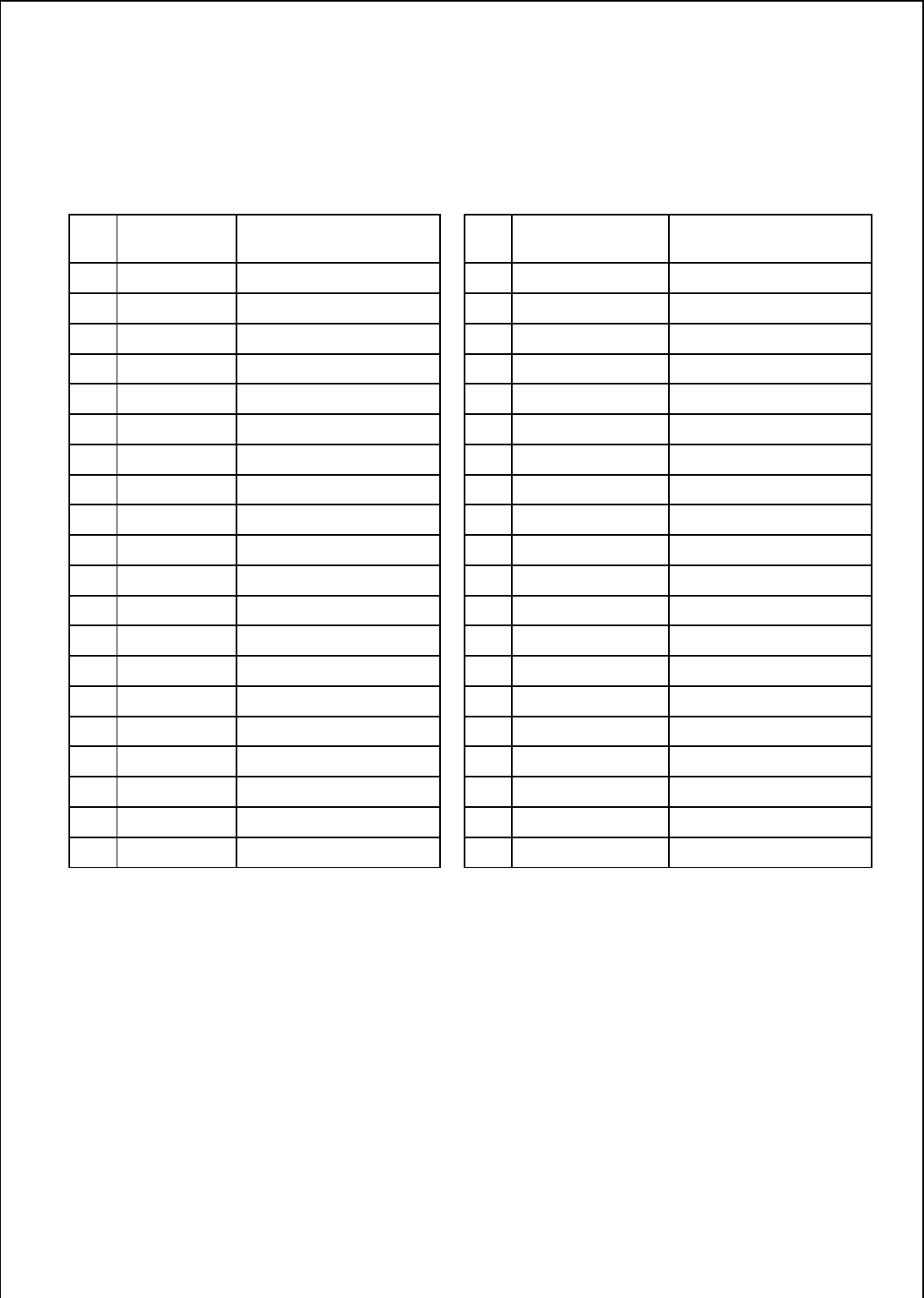
The Hirose DF12C board-to-board connector on the module is a 40-pin double-row receptacle.
The table below defines the pin functions. Note that this pin-out is as viewed from the underside of
the Module.
Pin
No.
Signal Description Pin
No.
Signal Description
1 Analogue 0 1.8v Max 2 GPIO1 I/O for Host.
3 Analogue 1 1.8v Max 4 GPIO2 I/O for Host
5 SPI_MISO SPI bus serial O/P 6 UART_RI ‘Ring’ Input or Output
7 SPI_CSB SPI bus chip select I/P 8 UART_DCD Input or Output
9 SPI_CLK SPI bus clock I/P 10 UART_DSR Input
11 GND 12 GPIO3/UART_DTR
I/O for Host
13 RESET Reset I/P * 14 GPIO4 I/O for Host & LED
15 GND 16 GPIO5 I/O for Host
17 SPI_MOSI SPI bus serial I/P 18 GND
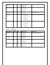
19 UART_CTS Clear to Send I/P 20 PCM_CLK PCM Clock I/P
21 UART_TX Transmit Data O/P 22 PCM_IN PCM Data I/P
23 UART_RTS Request to Send O/P 24 PCM_SYNC PCM Sync I/P
25 UART_RX Receive Data I/P 26 PCM_OUT PCM Data O/P
27 VCC_3V3 3.3V Monitor 28 N/C
29 VCC_5V 3.6V < VIN < 7.0V 30 GND
31 N/C 32 USB / RESERVED Do not connect
33 GPIO6 ** I/O for Host 34 USB / RESERVED Do not connect
35 GPIO7 ** I/O for Host 36 GND
37 GPIO8 ** I/O for Host 38 GND
39 GPIO9 I/O for Host 40 N/C
Notes:
* The reset circuitry within the BISM Serial Modules now incorporates a brown-out detector within
the module. Customers migrating from previous modules should check their implementation, as they
may be able to simplify their external power supply design. The reset line has a fixed 10kOhm pull
down resistor to ground.
** Pins 33, 35 and 37 were N/C on BISM1. Pin 39 was a 1V8 monitor. Designers migrating between
designs should be aware that these are now available as I/O. Default configuration is as an input
PIO lines can be configured through software to be either inputs or outputs with weak or strong pull-
ups or pull-downs. At reset, all PIO lines are configured as inputs with weak pull-downs.
UART_RX, UART_TX, UART_CTS, UART_RTS, UART_RI, UART_DCD and UART_DSR are all 3.3v level
logic. For example, when RX and TX are idle they will be sitting at 3.3V. Conversely for handshaking
pins CTS, RTS, RI, DCD, DSR a 0v is treated as an assertion.
Pin 6 (UART_RI) is active low. It is normally 3.3v. When a remote device initiates a connection, this
pin goes low. This means that when this pin is converted to RS232 voltage levels it will have the
correct voltage level for assertion.