


2 - 2
2.2 Program Set Commands
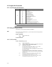
2.2.1 List of Program Set Commands
Command Type
Command Function
Set
SR
SA
SN
SW
SD
SY
SZ
SP
SK
ST
SL
SF
SG
SC
SM
SH
SX
MD
Sets the input range and display scale.
Sets the alarms.
Sets the engineering unit.
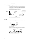
Sets the waveform span rate.
Sets the date and time.
Copies the channel settings.
Sets the discrete (zone) display.
Sets the partial expanded display.
Sets whether to display the scale values.
Sets the tag number.
Sets the trip level.
Sets the floppy disk format.
Sets the data file names.
Sets the LCD brightness and saver function.
Sets the messages.
Sets the number of division of the bar graph scale.
Sets wether to display the span rate and message menu.
Sets the waveform display and scale display.
Note
For restrictions concerning settings, refer to the instruction manual for the VR200.
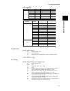
2.2.2 Setting the Range and Scale
(See Section 4.1 of the instruction manual for the VR200.)
SKIP
Skips scanning the specified channel, i.e., prevents that channel from being measured,
recorded and displayed.
Format: SRp1,mode
p1: Channel number (CC)
mode: SKIP
Example:SR01,SKIP
VOLT, TC, RTD, and DELT
Format: SRp1,mode, p2, p3, p4
p1: Channel number (CC)
mode: VOLT, TC, RTD, or DELT (difference computation between the
specified channel and the reference channel)
p2: Specification of the range
For mode VOLT: 20mV, 60mV, 200mV, 2V, 6V, or 20V
For mode TC: R, S, B, K, E, J, T, N, W, L, or U
For mode RTD: JPT or PT (or, optionally CU1, CU2, CU3, CU4,
CU5, CU6, or CU25)
For mode DELT: the reference channel number. Note that the
reference channel number must be lower than the channel number
specified in p1.
p3: Enter the low limit value of the display span within 5 digits
excluding the decimal point and the + or - sign.
p4: Enter the high limit value of the display span within 5 digits
excluding the decimal point and the + or - sign.