3 - 4
(4) Measured data
12345
Byte
A
2
A
1
A
4
A
3
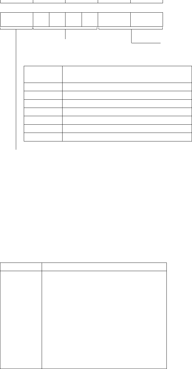
Alarm status
(for each level)
A1 to An correspond to statuses for levels 1 to 4.
Alarm status
Description
1
2
3
4
5
6
0 No alarm or the alarm function is set to OFF
Channel number (1 to 4)
Measured value *
H (occurrence of high limit alarm)
L (occurrence of low limit alarm)
h (occurrence of difference high limit alarm)
l (occurrence of difference low limit alarm)
R (occurrence of rate-of-change alarm on increase)
r (occurrence of rate-of-change alarm on decrease)
*Measured value
The order of the byte arrangement, whether to begin with the most significant byte
(MSB) or least significant byte (LSB), can be specified by the BO command.
Abnormal data:
7E7E is the data value output for + overrange.
8181 is the data value output for – overrange.
8080 is the data value output when the channel is skipped.
3.2.3 Output Format of Parameter Settings
When receiving the TS1, ESC T, and LF commands, the VR200 recorder sends the set
values of parameters in the following order (each set value is output in the same format
as the set command):
Communication Set Value(s) to Be Output
SR
SN
SA
SZ
SP
SK
SW
ST
SF
SL
SG
SM
SH
SX
SC
SS
EN
Range
Engineering unit
Alarms
Discrete (zone) display
Partial expanded display
Scale value indication
Waveform span rate
Tag numbers
Floppy disk format type
Trip levels
Data file names
Messages
Number of division of bar graph display
Waveform span rate and message menu display
LCD brightness and saver function
Summer/Winter setting
End of parameter settings output


