


2 - 6
2.2.8 Setting the Discrete (ZONE) Display
(See Section 4.7.1 of the instruction manual for the VR200.)
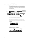
Format: SZp1, p2, p3
p1: Channel number (CC)
p2: Lower display boundary value (0 to 95)
p3: Upper display boundary value (5 to 100)
Example:SZ02, 30,50
This example results in the display for 0 to 100% of channel 2 in the band
from 30 to 50% of the scale.
Note
• The display bandwidth cannot be set to 5% or less.
• The lower display boundary must be less than the upper boundary.
2.2.9 Setting the Partial Expanded Display
(See Section 4.7.2 of the instruction manual for the VR200.)
Format: SPp1, p2, p3, p4
p1: Channel number (CC)
p2: Partial expanded display ON/OFF
p3: Percentage of the full display span which will be compressed (1 to
99%)
p4: Boundary value (lower display span + 1 to upper display span – 1).
Enter a numeric value excluding the decimal point.
Note
The decimal point position depends on the range (or scaling) setting. See also the input range table on Page 2-3.
Example:SP01, ON, 25, 0000
This example results in partial expanded display for channel 1 where the
value at 25% of the display scale corresponds with 0.000V.
2.2.10 Setting the Scale Value Indication On/Off (DISP_SCALE, only for VR200
with style number 1 or lower)
(See Section 4.7.3 of the instruction manual for the VR200.)
Format: SKp1, p2
p1: Channel number (CC)
p2: Whether to display the scale values.
Enter “ON” or “OFF”.
2.2.11 Setting the Tag
(See Section 4.7.4 of the instruction manual for the VR200.)
Format: STp1, p2
p1: Channel number (CC) for which you want to set a tag number
p2: Tag number (up to 7 characters)
Example:ST01, TAG1
This example sets the tag of channel 1 to “TAG1.”