1 - 4
If A < B, then signal = 1
If A > B, then signal = 0
1.4.1 Start-stop (Asynchronous) Communication
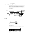
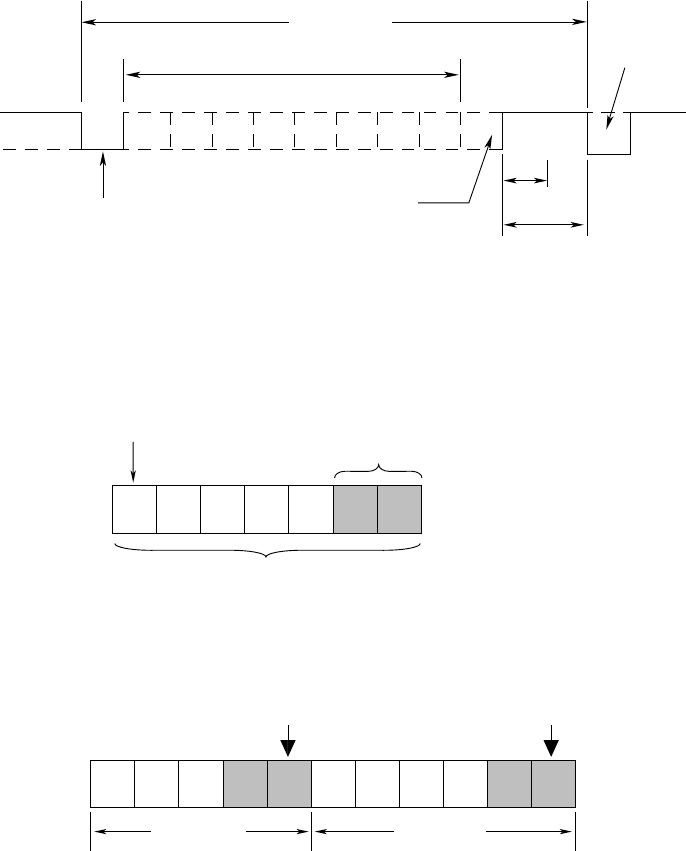
The built-in RS-422-A interface communicates based on the start-stop (asynchronous)
system. The start-stop system first adds the start bit to the head and then in turn adds
the data bits (7 or 8 bits), parity bit, and stop bit(s) to every transmission of each
character (see Figure 1.4). Define the address of the RS-422-A interface built in the
VR200 recorder, baud rate, data length, parity bit, and stop bit(s) in the SETUP mode
on the VR200 recorder.
The start bit is automatically added and thus need not be set.
One character
Data bits
(7 or 8 bits)
Parity bit: odd,
even or none
Stop bit
1
1 or 2
Start bit
Idle status of
the line
1
0
Line released due to
the idle status (broken
line) or continued by
the start bit of the next
data (solid line).
Figure 1.4 Configuration of Each Character in Start-stop System
1.4.2 Text
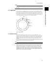
Each communication data usually contains more than one character, to which a
terminator character is appended. This is referred to as a text. See also Figure 1.5.
ABCDECRLF
One character
One text
Terminator
Figure 1.5 Structure of Text
The built-in RS-422-A interface identifies each text by regarding the reception of a
terminator as the end of the text. See also Figure 1.6.
A B CCRLF D E F GCRLF
Text 1 Text 2
Identifies text 1.
Identifies text 2.
Figure 1.6 Example of Two Texts Where Terminator Is CR/LF


