


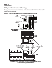
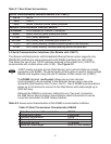

Table 2.1 Rear Panel Annunciators
Serial Communication Interface Section (For -C4EIT):
Pin 10 -Rx/Tx
Pin 9 +Rx/Tx
Pin 8 Return, Common Ground Shield connection
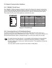
Network Communication Interface Section:
ETHERNET RJ-45 interface for 10BASE-T connection.
RESET Button: Used for power reseting the iServer.
C / ACT LED (Green) not active.
ON / NET LED (Green) Solid: Indicates good network link.
T / TX LED (Yellow) Blinking: Indicates transmitting data to the serial port.
R / RX LED (Green) Blinking: Indicates receiving data on the serial port.
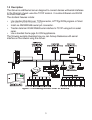
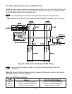
2.3 Serial Communication Interfaces (For Models with -C4EIT)
The iSeries controller/monitor with Embedded Ethernet Server option supports only
RS485/422 interfaces to slave instruments with RS485 interfaces (ex: i833-C24).
This allows the use of one TCP/IP address assigned to the master unit (-C4EIT) to
communicate with multiple slave units (-C24). See Figure 2.3.
-C4EIT master unit acts as hub (Web Server), but it cannot initiate an outside
connection with RS485. The serial portion of this option is used to slave multiple
RS485 units together using the one IP address of that master unit (-C4EIT).
The RS485 standard (multi-point) allows one or more devices
(multi-dropped) to be connected to the Ethernet Server using a two-wire
connection (half-duplex) +Rx/+Tx and –Rx/-Tx. Use of RS485 communications
allows up to 32 devices to connect to the Web Server with cable length up to
4000 feet long.
Although the RS485 is commonly referred to as a "two wire" connection,
the Web Server also provides a ground/return shield connection to use as
a common connection for EMI noise protection.
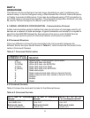
Table 2.2 shows some characteristics of the RS485 communication interface.
Table 2.2 Data Transmission Characteristics RS485
Data Transmission Characteristics RS485
Transmission Mode Differential
Electrical connections 2 wire
Drivers per line 32 drivers
Receivers per line 32 receiver
Maximum cable length 4000 ft (1200 meters)
5