


DBK215, pg. A-12
948894 Appendix A
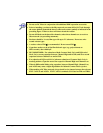
• Do not use RC filters in conjunction with additional DBK expansion accessories.
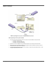
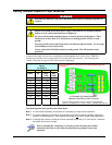
• Prior to installing a resistor to the filter network you must drill a 1/16” hole through
the center pinhole [beneath the board’s silkscreen resistor symbol] as indicated in the
preceding figure. Failure to do so will short-circuit the resistor.
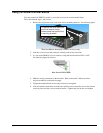
• Do not drill holes on the board for channels, unless those channels are to receive a
filter network (see preceding statement).
• Resistors should be ¼ watt, film-type with up to 5% tolerance. Do not use wire-
wound resistor types.
• A resistor value of 510 Ω is recommended. Do not exceed 510 Ω.
• Capacitors used are to be of the film dielectric type (e.g., polycarbonate or
NPO ceramic), above 0.001 µF.
• RECOMMENDED: For reduction of both Common Mode Noise and Differential
Mode Noise, use one capacitor between Channel High and AGND; and use a second
capacitor between Channel Low and AGND.
• For reduction of Differential Noise [when no reduction of Common Mode Noise is
needed] position a capacitor across the respective Channel High and Channel Low.
• When in Differential Mode, using capacitors between Channel High, Channel Low,
and AGND may cause a slight degradation of wideband Common Mode rejection.
• When making a RC filter network, always install a wire jumper between the relevant
FILT CAP LO and AGND. FILT CAP LO terminals are located on TB9 and TB10.