


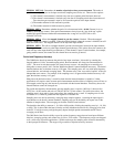
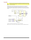
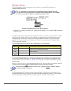
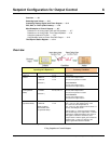
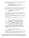

ENCODER: OPT[1:0]: This determines the encoder measurement mode: 1X, 2X, or 4X.
ENCODER: OPT3: This determines which signal latches the counter outputs into the data stream going
back to the /3000 Series board. Normally, the start of scan signal latches the counter outputs at the
beginning of every scan. The other option is to have the mapped signal latch the counter outputs. This
allows the user to have another signal control the latching of the count data, so the exact value of the
counter is known when an edge is present on another channel.
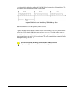
ENCODER: OPT4: This allows the mapped channel to gate the counter if desired. When the mapped
channel is high, the counter is enabled to count, when the mapped channel is low, the counter is disabled
(but holds the count value.) The mapped channel can be any other input channel.
ENCODER: OPT5: This allows the mapped channel to clear the counter if desired. OPT5 implements
the Z-function [described above], allowing the encoder reference to clear the counter. The counter is
cleared on the rising edge of the mapped channel.
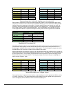
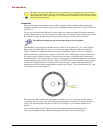
Encoder Wiring Diagrams
You can use up to two encoders with each 3000 Series board module in your acquisition system. Each A
and B signal can be made as a single-ended connection with respect to common ground.
Encoder wiring diagrams and example setup tables are included in the following pages; refer to them as
needed.
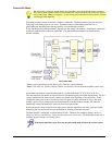
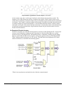
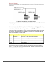
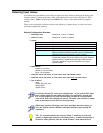
For Single-ended Connections:
For single-ended applications, the connections made from the encoder to the 3000 Series board are as
follows:
• Signals A, B, and Z connect to the Counter Inputs on 3000 Series board.
• Each encoder ground connects to GND.
• +5 V is available on the 68-pin SCSI connector for powering encoders.
Differential applications are not supported.
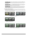
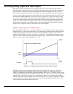
For Open-Collector Outputs: External pullup resistors can be connected to the 3000 Series
board’s counter input terminal blocks. A pullup resistor can be placed between any input channel
and the provided +5 V power supply.
Choose a pullup resistor value based on the encoder’s output drive capability and the input
impedance of the 3000 Series board. Lower values of pullup resistors will cause less distortion
but also cause the encoder’s output driver to pull down with more current.
DaqBoard/3000 Series User’s Manual 918494 Counter Input Modes 5-17