


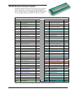
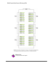


TB-100 Terminal Connector Option
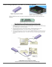
The TB-100 Terminal Connector option can be used to connect all
signal I/O lines that are associated with a DaqBoard/3000 Series
device. TB-100 connects to the DaqBoard’s 68-pin SCSI connector
via a 68-conductor cable: p/n CA-G55, CA-G56, or CA-G56-6.
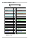
TB-100 Pinout The “Pin” column refers to the pin no. on the 68-Pin SCSI Connector.
Screw Terminals for TB2 Side Pin Screw Terminals for TB1 Side Pin
+5V Vcc (+5 VDC) 19 ACH0 Analog Input Channel 0 68
GND Digital Common
Note 1
ACH8 Analog Input Channel 8 34
A0 Digital I/O Line A0 18 AGND Analog Common
Note 2
A1 Digital I/O Line A1 52 ACH1 Analog Input Channel 1 33
A2 Digital I/O Line A2 17 ACH9 Analog Input Channel 9 66
A3 Digital I/O Line A3 51 AGND Analog Common
Note 2
A4 Digital I/O Line A4 16 ACH2 Analog Input Channel 2 65
A5 Digital I/O Line A5 50 ACH10 Analog Input Channel 10 31
A6 Digital I/O Line A6 15 AGND Analog Common
Note 2
A7 Digital I/O Line A7 49 ACH3 Analog Input Channel 3 30
B0 Digital I/O Line B0 14 ACH11 Analog Input Channel 11 63
B1 Digital I/O Line B1 48 AGND Analog Common
Note 2
B2 Digital I/O Line B2 13 ACH4 Analog Input Channel 4 28
B3 Digital I/O Line B3 47 ACH12 Analog Input Channel 12 61
B4 Digital I/O Line B4 12 AGND Analog Common
Note 2
B5 Digital I/O Line B5 46 ACH5 Analog Input Channel 5 60
B6 Digital I/O Line B6 11 ACH13 Analog Input Channel 13 26
B7 Digital I/O Line B7 45 AGND Analog Common
Note 2
C0 Digital I/O Line C0 10 ACH6 Analog Input Channel 6 25
C1 Digital I/O Line C1 44 ACH14 Analog Input Channel 14 58
C2 Digital I/O Line C2 9 AGND Analog Common
Note 2
C3 Digital I/O Line C3 43 ACH7 Analog Input Channel 7 57
C4 Digital I/O Line C4 8 ACH15 Analog Input Channel 15 23
C5 Digital I/O Line C5 42 XDAC3 Analog Output, DAC3 56
C6 Digital I/O Line C6 7 SGND Low Level Sense Common 62
C7 Digital I/O Line C7 41 POSREF +5 VDC Positive Reference 20
TTLTRG TTL Trigger Input 6 XDAC2 Analog Output, DAC2 55
GND Digital Common
Note 1
NEGREF - 5 VDC Negative Reference 54
CNT0 Counter Input CTR0 5 AGND Analog Common
Note 2
CNT1 Counter Input CTR1 39 XDAC0 Analog Output, DAC0 22
CNT2 Counter Input CTR2 4 AGND Analog Common
Note 2
CNT3 Counter Input CTR3 38 XDAC1 Analog Output, DAC1 21
TMR0 Timer Output 0 3 AGND Analog Common
Note 2
TMR1 Timer Output 1 37 XAPCR A/D Pacer Clock I/O 2
XDPCR DAC Pacer Clock I/O 1 GND Digital Common
Note 1
GND Digital Common
Note 1
EGND Earth Ground N/A
Note 1: Digital Common Pins on the SCSI connector are: 35, 36, and 40.
Note 2: Analog Common Pins on the SCSI connector are: 24, 27, 29, 32, 59, 64, and 67
DaqBoard/3000 Series User’s Manual 918494 Connections & Pinouts 2-3