


DBK215, pg. A-10
948894 Appendix A
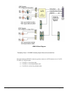
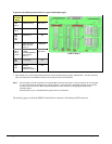
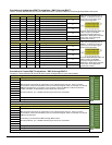
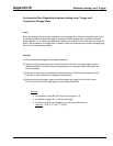
Correlation to Analog Input BNC Terminations – BNC 0 through BNC 7
“Virtual” Terminal Blocks TB13 and TB14 for ANALOG INPUT connect to TB9 and TB10 through the printed circuit board.
TB13 (“Virtual” Terminal Block) 68-Pin SCSI Connector, Pin Number and Description
BNC CH DIFF SE Pin SE = Single Ended ; DIFF = Differential Jumper Used
BNC0+ 0H 0 68 CH 0 IN (SE) / CH 0 HI IN (DIFF)
BNC0- 0L 8 34 CH 8 IN (SE) / CH 0 LO IN (DIFF)
J0
BNC1+ 1H 1 33 CH 1 IN (SE) / CH 1 HI IN (DIFF)
BNC1- 1L 9 66 CH 9 IN (SE) / CH 1 LO IN (DIFF)
J1
BNC2+ 2H 2 65 CH 2 IN (SE) / CH 2 HI IN (DIFF)
BNC2- 2L 10 31 CH 10 IN (SE) / CH 2 LO IN (DIFF)
J2
BNC3+ 3H 3 30 CH 3 IN (SE) / CH 3 HI IN (DIFF)
BNC0+ 3L 11 63 CH 11 IN (SE) / CH 3 LO IN (D DIFF)
J3
AGND N/A N/A * Analog Ground N/A
AGND N/A N/A * Analog Ground N/A
TB13 does not physically exist on
DBK215. A silkscreen of TB13 is
present as a visual aid to signal
routing and configuration.
A header located beneath TB14 and
TB16 is used to set the BNC
channels to Single-Ended or to
Differential. Simply place channel’s
2-pin jumper in the appropriate
position (SE or DIFF).
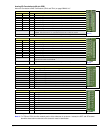
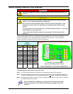
TB14 (“Virtual” Terminal Block) 68-Pin SCSI Connector, Pin Number and Description
BNC CH DIFF SE Pin SE = Single Ended ; DIFF = Differential Jumper Used
BNC4+ 4H 4 28 CH 4 IN (SE) / CH 4 HI IN (DIFF)
BNC4- 4L 12 61 CH 12 IN (SE) / CH 4 LO IN (DIFF)
J4
BNC5+ 5H 5 60 CH 5 IN (SE) / CH 5 HI IN (DIFF)
BNC5- 5L 13 26 CH 13 IN (SE) / CH 5 LO IN (DIFF)
J5
BNC6+ 6H 6 25 CH 6 IN (SE) / CH 6 HI IN (DIFF)
BNC6- 6L 14 58 CH 14 IN (SE) / CH 6 LO IN (DIFF)
J6
BNC7+ 7H 7 57 CH 7 IN (SE) / CH 7 HI IN (DIFF)
BNC7+ 7L 15 23 CH 15 IN (SE) / CH 7 LO IN (DIFF)
J7
AGND N/A N/A * Analog Ground N/A
AGND N/A N/A * Analog Ground N/A
TB14 does not physically exist on
DBK215. A silkscreen of TB14 is
present as a visual aid to signal
routing and configuration.
A header located beneath TB14 and
TB16 is used to set the BNC
channels to Single-Ended or to
Differential. Simply place channel’s
2-pin jumper in the appropriate
position (SE or DIFF).
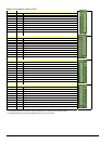
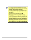
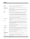
Correlation to Custom BNC Terminations – BNC A through BNC H
Pertains to Terminal Blocks TB15 and TB16 for Custom Configuration on a per-channel basis.
TB15 (“Routing” Terminal Block)
BNC CH Description
BNCA+
BNCA-
BNCB+
BNCB-
BNCC+
BNCC-
BNCD+
BNCD+
BNC channels A through D are configured on a per-channel basis by the user. TB15 is a routing
terminal block used to connect BNCs (A thru D) to the desired signals, which are selected via a second
DBK215 terminal block. For example: a user could run a wire from BNCA+ to TB4 screw terminal
“TMR0” and BNCA- to TB4 DGND to create a BNC timer connection.
Accessory Wire Kit, p/n 1139-0800 includes jumper wires and a screwdriver.
AGND Analog Ground *
AGND Analog Ground *
TB15
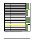
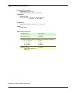
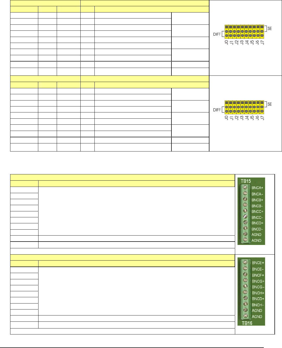
TB16 (“Routing” Terminal Block)
BNC CH Description
BNCA+
BNCA-
BNCB+
BNCB-
BNCC+
BNCC-
BNCD+
BNCD+
BNC channels E through H are configured on a per-channel basis by the user. TB16 is a routing
terminal block used to connect BNCs (E thru H) to the desired signals, which are selected via a second
DBK215 terminal block.
Customizing is as described for BNCA through BNCD above.
Accessory Wire Kit, p/n 1139-0800 includes jumper wires and a screwdriver.
AGND Analog Ground *
AGND Analog Ground *
TB16
* The following SCSI Pins connect to Analog Common: 24, 27, 29, 32, 55, 56, 59, 64, and 67.