


Digital Inputs and Outputs
Twenty-four TTL-level digital I/O lines are included in each of the DaqBoard/3000 Series boards. Digital
I/O can be programmed in 8-bit groups as either inputs or outputs and can be scanned in several modes
(see Input Scanning). Ports programmed as input can be part of the scan group and scanned along with
analog input channels, or can be asynchronously accessed via the PC at any time, including when a
scanned acquisition is occurring.
Two synchronous modes are supported when digital inputs are scanned along with analog inputs.
o Scanning digital inputs at the start of each scan sequence. In this mode the digital inputs are
scanned at the start of each scan sequence, which means the rate at which they are scanned is
dependent on the number of analog input channels and the delay period. For example, if 8 analog
inputs were enabled with a 0 delay period, then the digital inputs in this mode would be scanned at
once per 8µsec, i.e., 125 kHz.
o Scanning digital inputs synchronously with every analog input channel. In this synchronous
mode, the enabled digital inputs are scanned synchronously with every analog input channel. So in
the preceding example the digital inputs would be scanned at once per µsec, or 1 MHz. If no
analog inputs were being scanned the digital inputs could be scanned at up to 12 MHz.
Digital Outputs and Pattern Generation
Digital outputs can be updated asynchronously at anytime before, during or after an acquisition. Two of the
8-bit ports can also be used to generate a 16-bit digital pattern at up to 12 MHz. The DaqBoard/3000 Series
boards support digital pattern generation via Bus Mastering DMA. In the same manner as analog output,
the digital pattern can be read from PC RAM or a file on the hard disk. Digital pattern generation is
clocked in the same four modes as described with analog output.
The ultra low-latency digital output mode allows a digital output to be updated based on the level of an
analog, digital or counter input. In this mode, the user associates a digital output bit with a specific input,
and specifies the level of the input where the digital output changes state. The response time in this mode is
dependent on the number of input channels being scanned, and can typically be in the range of 2 to 20
µsec.
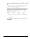
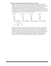
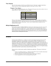
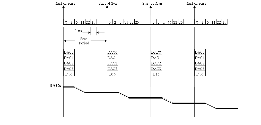
Example 5: Analog channel scanning of voltage inputs and streaming analog outputs
The figure below shows a simple acquisition. The scan is programmed pre-acquisition and is made up of 6
analog channels (Ch0, Ch2, Ch5, Ch11, Ch22, Ch25.) Each of these analog channels can have a different
gain. The acquisition is triggered and the samples stream to the PC via DMA. Each analog channel
requires one microsecond of scan time therefore the scan period can be no shorter than 6 us for this
example. The scan period can be made much longer than 6 us, up to 19 hours. The maximum scan
frequency is one divided by 6us or 166,666 Hz.
DaqBoard/3000 Series User’s Manual 988093 Daq Systems and Device Overviews 1-11