


Connection Tips
CAUTION
Turn off power to the host PC and externally connected equipment prior to connecting
cables or signal lines to DBKs. Electric shock or damage to equipment can result even
under low-voltage conditions.
Take ESD precautions (packaging, proper handling, grounded wrist strap, etc.)
Use care to avoid touching board surfaces and onboard components. Only handle
boards by their edges (or ORBs, if applicable). Ensure boards do not come into
contact with foreign elements such as oils, water, and industrial particulate.
1. Ensure power is removed from all device(s) to be connected.
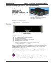
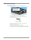
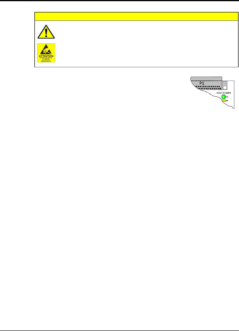
2. As soon as the DBK215 cover is removed, verify that the Host
Power LED is “Off.” See figure at right for location.
3. Observe ESD precautions when handling the board and making
connections.
4. You do not need to remove the cover unless you need to
access a terminal block, customize an RC filter network,
or set a BNC channel to Single-Ended mode or to Differential
mode (via Jumpers J0 through J7). Information regarding these
tasks follows shortly.
Location of DBK215’s
Host Power LED
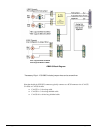
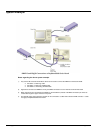
5. DBK215’s 68-pin SCSI (P5) connector typically connects to a board’s SCSI connector via a
CA-G55, CA-G56, or CA-G56-6 cable.
o CA-G55 is a 3-foot long cable.
o CA-G56 is a 3-foot long shielded cable.
o CA-G56-6 is a 6-foot long shielded cable.
6. Refer to the separate CE Cable Kit instructions that are included with the associated CE cable
kit. Refer to the Declaration of Conformity in regard to meeting CE requirements.
Appendix A 948894 DBK215 A-3