


OM-550 u32u
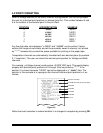
4.14 VOLTAGE INPUT SCALING
Any of the input channels (1 through 5) may be programmed as Voltage channels.
Each Voltage channel includes unique m and b constants for "scaling" data to your
application. These constants default to +1.00000 and 000000, respectively, when the
channel is first programmed as a Voltage channel but the user may reprogram them as
necessary. The following pages include examples for common transducers.
4.14.1 MATCHING TRANSDUCERS TO THE OM-550
Some transducers provide a "voltage" output; others provide a "current" output.
This section explains how to use resistors to match either output to the input.
Currents must be converted to a voltage and voltages must be attenuated (reduced) if
they can exceed the maximum input (±2.0000 VDC). This process is called Matching,
which means converting or attenuating the transducer's output to an acceptable level
without overloading it.
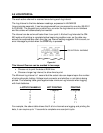
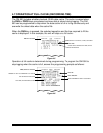
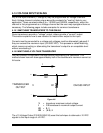
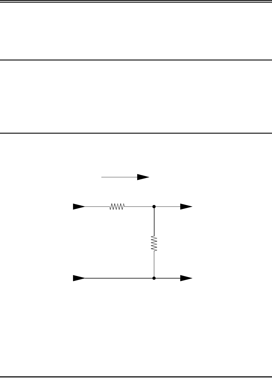
4.14.2 MATCHING A VOLTAGE TRANSDUCER
Use two resistors to attenuate a voltage without overloading the transducer. The
method shown here will draw approximately half of the transducer's maximum current at
full-scale.
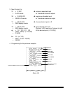
R1V OM-550 INPUT
I
TRANSDUCER
OUTPUT
+
-
R2
Figure 4-8
V = transducer maximum output voltage.
I = 1/2 transducer's maximum output current.
R1 = 2 / I
R2 = (V-2) / I
The ±10 Voltage Probe (P/N E29-0050-35) uses this technique to attenuate ±10 VDC
signals to the input range of ±2 VDC.