


1-2SectionLink Adapters
2
1-1 Nomenclature
Names of specific OMRON products, as well as generic names for groups of
OMRON
products, are capitalized in this manual. Unit is also capitalized when
it
refers either specifically or generically to an OMRON product. For convenience,
prefixes
are omitted from model numbers of Link Adapters and Repeater Units.
“(P)”
in a model number
indicates two Units, one with the P and one without. See
the
Appendix for a complete list
of all products covered in this manual, along with
their
full model numbers. In addition, abbreviations are used for certain Units. In
this manual, PC always means Programmable Controller; Master means Re-
mote I/O Master Unit; and Slave means Remote I/O Slave Unit.
1-2 Link Adapters
Link Adapters are used to interconnect system devices such
as host computers,
PC
Link Units,
Host Link Units, and Remote I/O Units, and/or to convert between
wire cable and optical fiber cable.
Using optical links between Units provides greater transmission distance and
noise resistance. In addition, Link Adapters provide inputs to bypass a Unit
which
is improperly connected or which suf
fers a power interruption, thereby al
-
lowing other Units connected in series to continue operating normally.
Some
Link Adapters can ensure that a System will not begin operating until, for
example, a particular Subsystem has started up.
There
are various models of Link Adapters to perform a variety of functions. For
example,
the Link Adapter
generally used for connecting PC Link Systems is the
AL001, but when optical cable is used it is replaced by combinations of the
AL002-(P)E and AL004-(P)E.
Link Adapter AL002-(P)E is used to branch optical cables; the AL004-(P)E is
used to convert between optical and wire cables; and the AL005-(P)E and
AL006-(P)E
are used for branching and/or converting between
dif
ferent types of
optical
fiber cables. Link Adapter AL007-P is used exclusively
in Wired Remote
I/O Systems.
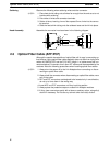
Link
Adapters
AL002-(P)E, AL005-(P)E, and AL006-(P)E have auxiliary power
input
terminals which can be connected
to a battery to ensure continued opera
-
tion even when the AC power supply is cut of
f. (See
2-5 Backup Power Supply
.)
Link
Adapters AL002-(P)E and AL006-(P)E have repeater input terminals. (See
2-6 Link Adapter Repeater Input
.)
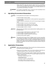
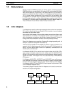
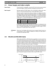
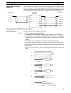
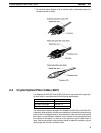
The
following diagram illustrates how Link
Adapters can be used to connect sev
-
eral Units in a simple configuration.
Link
Adapter
Rack with
linkable Unit
Rack with
linkable Unit
Link
Adapter
Rack with
linkable Unit
Link
Adapter
Rack with
linkable Unit