


!
2-2SectionRS-422 and RS-232C Cable
6
2-1 Power Supply and Cable Lengths
For
all but AL001 Link Adapters, connect the
AC hot line to the common terminal
of the Link Adapter. A fuse is internally connected to the common line.
Maximum
length for RS-232C cable is 15 m. For RS-422 it is 500 m, with a maxi
-
mum of 10 m for any given branch line. For RS-485 cable it is 200 m.
Maximum
lengths for optical fiber cables connected to Link Adapters are deter
-
mined
by the type of
cable and the particular model of Link Adapter employed.
Link
Adapters whose model numbers are
followed by “-P” can be connected to
either APF (all-plastic optical fiber) or PCF (plastic-clad optical fiber) cable.
Those without “-P” can be connected only to PCF cable. The model numbers,
cable types, and transmission distances are related as follows:
Cable Model No. With P Model No. Without P
APF
20 m
Not connectable
PCF
200 m 800 m
If transmission distances over 800 meters are required, it is necessary to use
AGF
(crystal optical fiber) cable, which calls for the
use of specific Link Adapters
(see
1-4 General Specifications
). For calculating maximum length for AGF
cable, see
2-4 Crystal Optical Fiber Cable (AGF
).
Caution Never use a Link Adapter with its terminal cover removed. Keep the cover se-
curely
attached.
If the Link Adapter is installed in an office or on a desk, take ex
-
tra care to avoid electrical shock.
2-2 RS-422 and RS-232C Cable
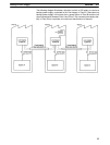
When
using optical fiber or RS-422 cable, it is possible to connect several Host
Link Units to one host computer. When RS-232C cable is used, however, the
connection
must either be on a one-to-one basis or a Link Adapter must be used
to convert to optical or RS-422 cable. As described below, wiring will vary de-
pending
on whether a Host Link Unit is connected directly to a host computer or
whether it is connected indirectly through a Link Adapter.
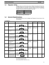
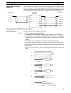
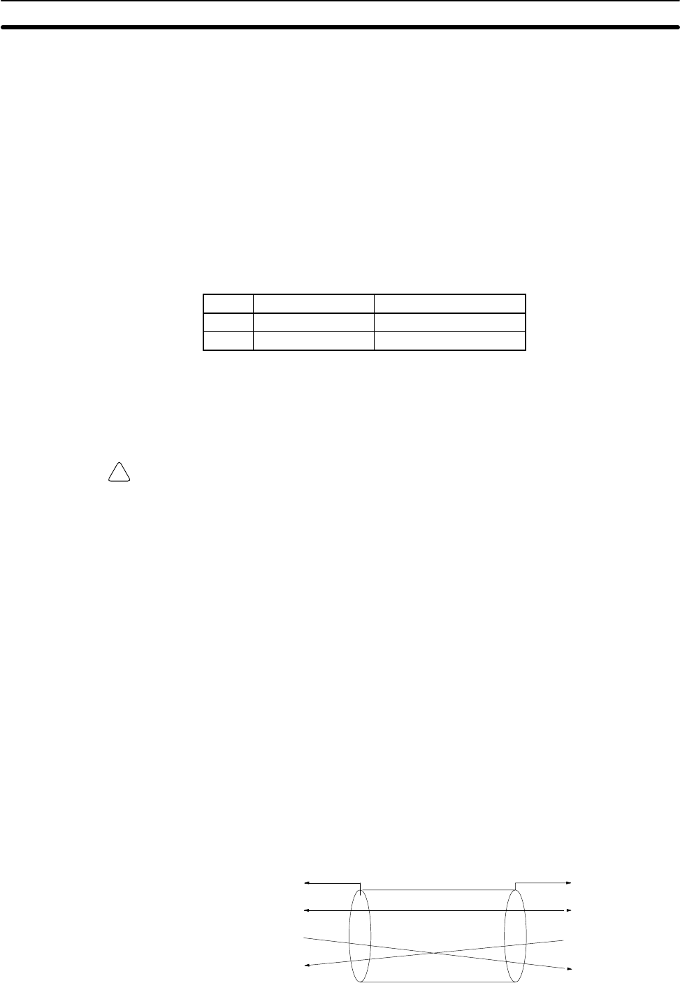
When
a Host Link Unit is connected one-to-one to a host computer
, with no
Link
Adapter,
and RS-232C cable is being used, connect the SD (send data) terminal
of
the host computer to the RD (receive data) terminal of the Host Link Unit. Like
-
wise, connect the RD terminal of the host computer to the SD terminal of the
Host
Link Unit. When using RS-422 cable,
the SDA and RDA terminals and the
SDB
and RDB terminals should be connected in a similar way
. The following dia
-
gram illustrates the proper connections when using RS-232C cable.
FG
SG
SD
RD
FG
SG
SD
RD
Host
Link Unit
Host computer
1
7
2
3
1
7
2
3
Pin No. Symbol Symbol Pin No.
Power Supply
Cable Lengths