


2-2SectionRS-422 and RS-232C Cable
7
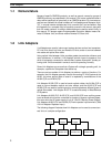
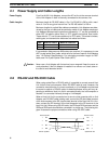
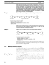
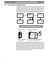
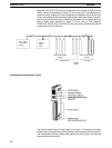
When
using a Link Adapter
, connect both RS-232C and
RS-422 cable straight
across,
as shown in the following diagram. Here the SD terminal of the host
com
-
puter,
for example, is connected to the SD terminal of the Link Adapter
. See
5-4
Link Adapter AL004-(P)E
for the internal configuration of the Link Adapter.
FG
SG
SD
RD
FG
SG
SD
RD
Host
computer
1
7
2
3
7
2
3
Link Adapter
AL004-(P)E
1
FG
SG
SDA
SDB
7
3
9
5
3
9
5
7
Host Link Unit
RDA
RDB
6
1
6
1
FG
SG
SDA
SDB
RDA
RDB
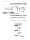
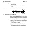
Wiring RS-232C and RS-422 Cable Connectors
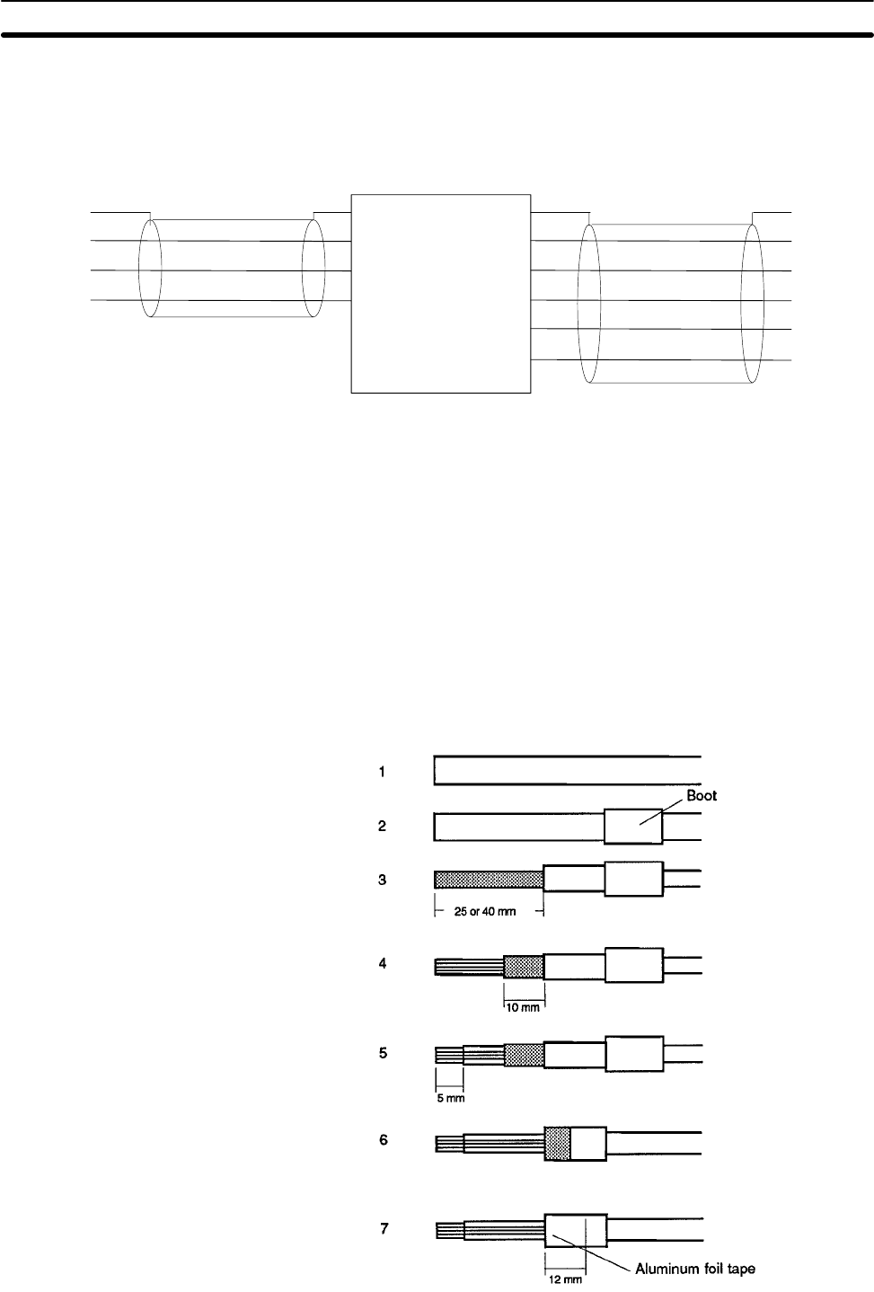
Prepare cables as follows before soldering:
1, 2, 3...
1. Cut the cable to the required length.
2. Thread the end of the cable through a boot at least 50 mm up the cable.
3. Being
careful not to
damage the braiding underneath, use a razor blade to
cut
away 25
mm of sheath for an RS-442 cable or 40 mm for an RS-232C
cable.
4. Using scissors, cut away all but 10 mm of the exposed braiding.
5. Using wire strippers, remove the covering from the last 5 mm of all wires.
6. Move
the boot to the
cut edge of the sheath and fold the braiding back over
the end of it.
7. Wrap
aluminum foil tape 1 1/2 turns over the top of the braiding on top of the
boot.
Connecting Link Adapter
AL004-(P)E
Cable Preparation