


4-3SectionOptical Remote I/O Systems
20
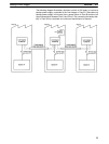
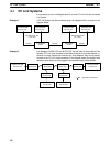
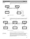
As
shown in Example 3, more than one Optical Host Link Unit can be
connected
in
series using optical fiber cables. However
, if any failure (power failure, discon
-
nection,
etc.) occurs in one of the Units, all the subsequent Host Link Units will
also
cease to operate.
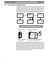
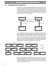
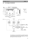
This can be prevented by using Link Adapters such as the
AL002-(P)E
as shown below
. These Link Adapters bypass any malfunctioning
Host Link Unit, thereby allowing the rest of the system to operate normally. In
other words, even if a power failure occurs in a Host Link Unit connected to a
branch
line of a Link Adapter
, signals are still transmitted to the other Host Link
Units.
Link
Adapter
AL004-(P)E
Host computer
RS-422 or RS-232C
C-Series PC
with
Optical Host
Link Unit
Optical fiber (APF/PCF)
C-Series PC
with
Optical Host
Link Unit
C-Series PC
with
Optical Host
Link Unit
C-Series PC
with
Optical Host
Link Unit
C-Series PC
with
Optical Host
Link Unit
.
Optical fiber (APF/PCF)
Link Adapter
AL002-(P)E
Link Adapter
AL002-(P)E
Link Adapter
AL002-(P)E
Link Adapter
AL002-(P)E
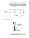
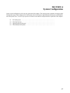
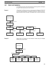
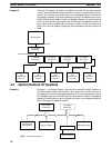
4-3 Optical Remote I/O Systems
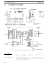
Example
1: In an Optical System, Units can be connected in
series. However
, if
any failure (power failure, disconnection, etc.) occurs
in one of the Units, all of
the
subsequent Units will also cease to operate. This can be prevented by using
Link Adapters such as the AL002-(P)E as shown below. These Link Adapters
bypass
any malfunctioning Unit connected to a branch line, thereby allowing the
rest of the system to operate normally.
Link
Adapter
AL002-(P)E
CPU Rack with
Optical Master
Optical Link Rack Optical Slave Rack
Optical fiber (APF/PCF)
C120 I/O Link Rack
C120 CPU Rack
Link Adapter
AL002-(P)E
Example 3
Example 1