


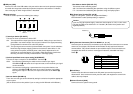
RBus Selector Switch [BUS A/B /F.F.]
This selects the bus switching system.
A/B: Set here when undertaking bus operations using the A/B bus system.
F.F.: Set here when undertaking bus operations using the flip-flop system.
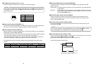
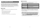
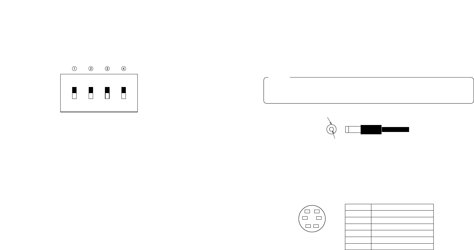
LDC Power Input Terminal [DC 12V IN]
Apply 12-V DC power. (Use the AC adaptor AW-PS505.)
✽The AW-CA4T1 cable (sold separately) is required.
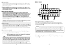
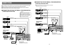
:Tally/Intercom Connectors [TALLY & INCOM 1, 2, 3, 4, 5]
Use these jacks to connect the Live Switcher to the tally/intercom connectors on a camera
control unit, for example, WV-RC700A or WV-RC550, for tally control and intercom
communication. Tally control is based on open collector output. These connectors are
compatible with either the 3-wire or 4-wire type of intercoms, selectable with Setup
Switch K.
aCord Clamp
Used to clamp the cable connected to the DC power input terminal to prevent its
disconnection. Once remove the screw, pass the cable, and retighten the screw till the
cable is securely clamped.
sGround Terminal [GND]
Connect this to the system frame ground.
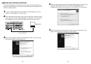
JUSB port [USB]
Connect one end of the USB cable to this port and the other end to the personal computer
to transfer the image data created by the personal computer to this switcher. For details,
refer to the page on which image transfer is described.
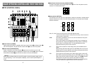
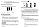
KSetup switches
These are used to perform the following four settings.
QFrame Sync Switch [FS ON/FF]
This sets the frame synchronizer to ON or OFF.
ON: The asynchronous 5 input signal can be connected. A delay of up to one frame is
generated in the switcher output. Due to what is involved in the signal processing,
the signal band is narrower than at the OFF position.
OFF: The input signal source must be synchronized with the system. Use the switcher's
black burst signal output to apply genlock to the camera or other device. In this
case, perform the phase (horizontal phase, color phase) adjustments for the
genlock at the connected device. In this mode, analog processing is performed
internally, and there is virtually no deterioration in the image quality.
WGenlock input/Black burst output setting [GLIN/BBOUT]
This sets the input or output for the GLIN/BBOUT Connector D.
GLIN: Set here when genlocking the switcher with an external sync signal.
GLIN/BBOUT D now serves as an input connector, and an external sync signal
can be connected.
BBOUT: Set here when configuring a system based on the synchronization to the
switcher. GLIN/BBOUT D now serves as an output connector, and a black
burst signal is output. In this case, the output is the same as the BBOUT F
signal.
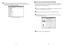
EIntercom Switch [INCOM 3/4]
The 3-wire or 4-wire type can be selected by setting the switch to the position appropriate
to your system.
(Set the switch to the 3-wire position if you are using the WV-RC700A or WV-RC550.)
1918
Pin No. Signal
1 MIC+
2 MIC–/COMMON
3 PHONE+
4 PHONE–/COMMON
5 TALLY
6GND
ON BBOUT
OFF GLIN
A/B
F.F.
FS GLIN
/BBOUT
INCOM BUS
3-wire
type
4-wire
type
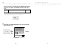
If you are using other power supply, make sure that it outputs 12 V DC, 2.5 A or more.
The plug has GND on the inside and +12 V outside. (Be careful of the positive and
negative polarities.)
Caution
Positive (+)
Negative (–)
6
4
2
5
3
1