


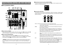
DGenlock Input/BB Output Connector [GLIN/BBOUT]
In compliance with the setting of the SETUP switch K, either the genlock input or BB
output is selected.
Genlock input: To apply genlock to the switcher, connect this signal to the signal generator
or other device.
BB output: At this position, the BB sync signal is output to apply genlock to a camera or
other input device by synchronizing it to the switcher. In this case, the same
signal as BBOUT F is output.
FBlack Burst Signal Output Connector [BBOUT]
Used to externally synchronize a input device connected to the Live Switcher. When
externally synchronizing two or more devices, distribute the black burst output to them
using a video distributor (VDA).
GY/C Video Output Connector [PGM Y/C OUT]
This connector delivers the Y/C signal video output which has the same function as the
video output signal A.
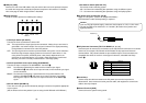
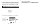
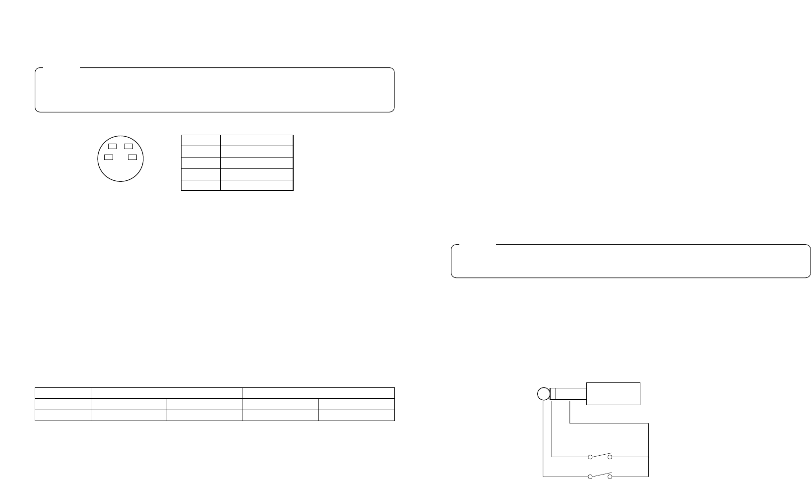
HAuto Take External Input Jack [EXT TAKE]
Use it for external auto take by applying a contact input. The operation is the same as when
using Auto Take Switch u and Key Auto Switch I.
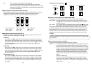
✽Use an M3.5 stereo single head plug for connection with this unit.
Connect the switches as shown below.
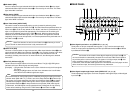
]Y/C Signal Input Jacks [Y/C IN 1, 2, 3, 4, 5]
Connect YC signals to these jacks in using them as video input signals.
AVideo Output Connectors [PGM OUT 1, 2]
Two sets of composite signals (BNC) consisting of the switcher's main output together with
the wipe, mix, key or other effects added are output from these output jacks.
SPreview Output Connector [PVW OUT]
When the switcher is used for live applications, this connector enables the next operation to
be previewed. (LOOK AHEAD PREVIEW)
• While the Fader Lever is at the A-bus side and A-bus signals are output, the B-bus signals
are output to the PVW OUT Connector, and the images can be previewed.
• When the PGM OUT Connectors are in the key OFF status, the PVW OUT Connector is
set to the key ON status and the key synthesis status can be previewed.
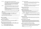
The table below shows the correlation between the program output and preview output
statuses.
1716
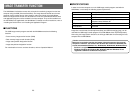
Do not connect a BNC coaxial cable to Video Signal Input Jack p in case of connecting
YC signals to Y/C Signal Input Jack ]. Use either composite signals or YC signals as
video input signals.
Caution
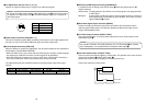
Bus selection Key ON/OFF
PGM OUT A-bus selected B-bus selected Key ON Key OFF
PVW OUT B-bus output A-bus output Key OFF Key ON
AUTO TAKE
KEY AUTO
Due to what is involved in the signal processing, the Y/C video output G has a phase
which is delayed by 1 line compared with the composite video output A.
Caution
4
2
3
1
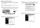
Pin No. Signal
1Y GND
2 C GND
3Y
4C