


1312
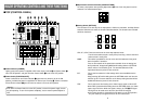
KEY AUTO: This switch is used to set the key synthesis to ON or OFF.
When it is pressed, it lights, and key synthesis is performed for the text, etc.
KEY AUTO U is used to set the transition time for the key synthesis. When
the switch is pressed again, it goes off, and the input signals used for the
key synthesis will be synthesized as they are with the base image but,
depending on the level of the input signals, it may not be possible to
achieve clean and clear images.
SOURCE: This selects whether to use the VIDEO IN 5 signal or image in the frame
memory as the source material for the key synthesis. In terms of the key
signals, use black base level signals, and provide a source with white
characters.
A source with color characters can also be synthesized with a black base
but, depending on the level of the character signals, it may not be possible
to achieve clean and clear images.
(By inverting the polarity of the key signals, images with a white base level
can also be synthesized. For details on key reversal, refer to SETTING R.)
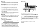
OIntercom Jack [INCOM]
Connect an intercom headset to this terminal. Use the recommended headset (made by
Ashida Onkyo MT-12MFB-03).
PIntercom Volume [INCOM LEVEL]
To adjust the volume of the headset speaker connected to Intercom Jack O. Turning it
counterclockwise decreases the volume, and turning it clockwise increases it.
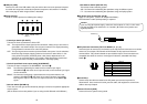
{Genlock Phase Controls [GEN-LOCK PHASE]
Connect a signal generator or other such instrument to GLIN/BBOUT D, and use these
controls to adjust the phase when genlock is to be initiated. These controls need not be
adjusted when genlock is not going to be initiated.
H: This is used to adjust the horizontal sync phase.
SC: This is used to adjust the subcarrier phase coarsely.
SC FINE: This is used to adjust the subcarrier phase finely.
Adjusting the horizontal phase:
Monitor the waveforms of the genlock signal (black burst signal) and video
signal output using a dual-trace oscilloscope (or waveform monitor), and adjust
the H Control in such a way that the horizontal phase is aligned.
Adjusting the subcarrier phase:
Select the color bars of the switcher. Using the signal generator as a reference,
adjust the SC Control and SC FINE Control to align the color phase. A more
accurate adjustment can be achieved using a vectorscope.
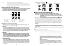
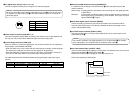
}A-Bus Input Selection Switches
To select A-bus video signals. When a switch is pressed, it lights and indicates that the
corresponding signal is selected.
qB-Bus Input Selection Switches
These are used to select the B-bus video signals. When a switch is pressed, it lights to
indicate that the corresponding signal is selected.
Depending on the operation mode, the switches may light with full or half brightness.
Full brightness: When the selected input is being output to PGM OUT.
Half brightness: When the switch is selected but the selected input is not being output
to PGM OUT.
[Example] When the Fader Lever is at the A-bus side, the A-bus signals are output so that
the A-Bus Input Selection Switches will light with full birghtness, but the B-bus
signals are not output so that B-Bus Input Selection Switches will light with half
brightness.
wFreeze indicator [FRZ]
This LED lights to indicates that the VIDEO IN 5 signal is frozen. Bear in mind that since
the image remains frozen while it is lighted, the switcher output will not change even when
the input signal has changed.
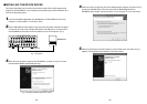
eInput 5/FMEM Selector Switch [FMEM]
This is used to select the signal which has been input to VIDEO IN 5 or the internal frame
memory. When the switcher is used for the first time and the frame memory has been
selected, the factory setting screen is output. By transferring image data from a personal
computer to the frame memory, the images and text created by the user can be output. For
details, refer to the page on which image transfer is described.
rBLACK/COLOR/BAR Selector Switch [BLACK/COLOR/BAR]
This is used to select BLACK (black level signal), COLOR (color background) or BAR (color
bar). When COLOR is selected, one of nine colors can be selected. For details on how to
select the color, refer to the section on “T Color Background Color Selector Switch
[COLOR]”.
A 100% white signal is output at the factory setting.
Follow the procedure below to keep the key synthesis on the PVW screen at the OFF
setting at all times.
1. Press both the SETTING Button R and COLOR Button T at the same time.
2. With the two buttons in step 1 held down, press the KEY AUTO Button.
The KEY AUTO Button lamp now lights.
To turn the key synthesis on the PVW screen back to the ON setting, repeat the same
steps. The KEY AUTO Button lamp will then go off.
Note