


Appendix
67
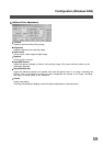
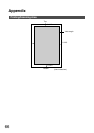
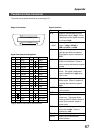
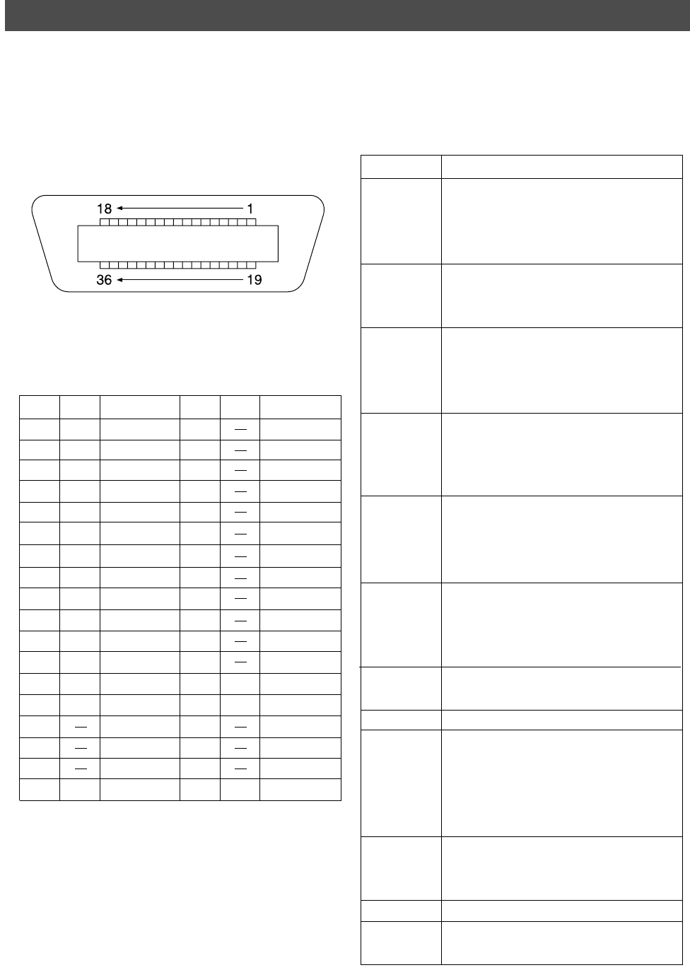
Parallel Interface Connector
The printer has a parallel interface for connecting to PC.
Shape of Connector
Signal lines and pin arrangement
*Signal used for bidirectional communication
No. I/O
Signal name
No. I/O
Signal name
1 I /STB 19 GND
2 I/O DATA0 20 GND
3 I/O DATA1 21 GND
4 I/O DATA2 22 GND
5 I/O DATA3 23 GND
6 I/O DATA4 24 GND
7 I/O DATA5 25 GND
8 I/O DATA6 26 GND
9 I/O DATA7 27 GND
10 O /ACK 28 GND
11 O BUSY 29 GND
12 O PE 30 GND
13 I SELECT 31 I /INIT
14 O /AUTOFD* 32 O /FAULT
15 Not used 33 Not used
16 GND 34 Not used
17 GND 35 Not used
18 O VCC 36 I /SELIN*
Signal functions
Signal name
Function
/STB Signal for sending data to printer.
Steady-state value is High. Printer
reads data until this signal becomes
from Low to High.
DATA0 to Input signal for receiving 8-bit data.
Data7 Logic 1 is High. DATA0 is
LSB and DATA 7 is MSB.
/ACK Signal indicating that printer has
read data into device completely.
This signal is output in response to
/STB.
BUSY Signal indicating that printer is
unable to receive data. Printer is
able to receive data when this signal
is Low.
PE Signal indicating Paper Out of
printer. This signal is Low when
paper is loaded and is High when
paper is out.
SELECT Signal indicating that printer is under
online status. Printer is capable of
receiving data when this signal is
High.
/AUTFD Signal used for bidirectional
communication
GND Ground
VCC Signal indicating that the power of
printer is on. This signal allows
verifying ON/OFF status of power of
printer and connection status of
printer cable.
/INT Signal for initializing printer. Steady-
state value is High. Printer is
initialized by Low.
/FAULT Signal indicating that printer is faulty.
/SELIN Signal used for bidirectional
communication