


PANDUIT® DPoE™ Power Patch Panel User’s Guide Issue 2.2
Part Number: PN378A
12
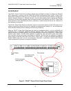
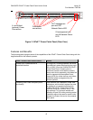
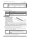
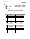
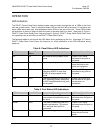
8. Fan out all four twisted pairs in the specified wiring
sequence (see color-coded wiring positions in Table 4:
Color-Coded Wire Positions for 802.3af-2003
Compliant Devices and Table 5: Color-Coded Wire
Positions for Alternate PoE Devices below). The
colors are also displayed on the Wiring Template
Label, already installed on the back of the DPoE™
Power Patch Panel.
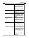
The DPoE™ Power Patch panel supports standard IEEE 802.3af-2003 devices as well as
alternate PoE devices consistent with the Cisco legacy devices.
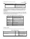
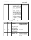
Table 4: Color-Coded Wire Positions for 802.3af-2003 Compliant Devices
Pin
Outs EIA/TIA 568A
Pin
Outs EIA/TIA 568B
5 WHITE/BLUE 5 WHITE/BLUE
4 BLUE 4 BLUE
1 WHITE/GREEN 1 WHITE/ORANGE
2 GREEN 2 ORANGE
3 WHITE/ORANGE 3 WHITE/GREEN
6 ORANGE 6 GREEN
7 WHITE/BROWN 7 WHITE/BROWN
8 BROWN 8 BROWN
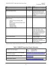
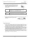
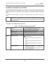
Table 5: Color-Coded Wire Positions for Alternate PoE Devices
Pin
Outs EIA/TIA 568A
Pin
Outs EIA/TIA 568B
5 WHITE/BROWN 5 WHITE/BROWN
4 BROWN 4 BROWN
1 WHITE/GREEN 1 WHITE/ORANGE
2 GREEN 2 ORANGE
3 WHITE/ORANGE 3 WHITE/GREEN
6 ORANGE 6 GREEN
7 WHITE/BLUE 7 WHITE/BLUE
8 BLUE 8 BLUE
NOTE:
The DPoE™ Power Patch Panel can terminate most 22-24 AWG solid or stranded
IWC wire with a .050” (1.27mm) max o.d. either PVC or Plenum rated.