


PANDUIT® DPoE™ Power Patch Panel User’s Guide Issue 2.2
Part Number: PN378A
13
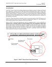
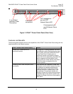
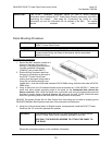
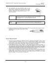
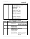
9. Lay conductors into the punchdown slots for the
specified port using the correct wiring sequence. Cable
jacket removal should be minimized to the extent
possible. Conductor untwist should be within ½” (12.7
mm) of termination.
WARNING:
NEVER TOUCH UNINSULATED COMMUNICATIONS WIRING OR
TERMINALS UNLESS THE COMMUNICATION LINE HAS BEEN
DISCONNECTED AT THE NETWORK INTERFACE.
NOTE:
Never install wiring in a slot previously used for a larger gauge wire.
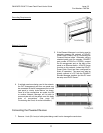
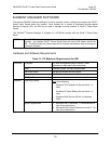
10. Using the punchdown tool (PANDUIT part number PDT110), punch down the connector into the
punchdown slots on the back of the DPoE™ Power
Patch Panel.
Power Requirements
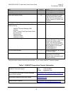
11. If the panel is being powered by a PANDUIT® DPoE™ Power Brick (See page 8, Table 1: Power
Supplies Available from PANDUIT Corp for a list of available powering options), skip to Powering
Up the DPoE™ Power Patch Panel Section below, since the brick is equipped with a matched
keyed power connector that will fit the power connector on the back of the panel.
12. If the PANDUIT® DPoE™ Power Chassis or a direct 48VDC source is powering the panel, cut
the 10-foot power harness to length then strip the ends of the leads to 5/16” (7.9 mm). Connect
the stripped ends of the power harness into the PANDUIT® DPoE™ Power Chassis. If the power
harness is not long enough or the 48VDC source requires a specific connector, strip the ends of
the wire to the same strip length, being careful not to damage the conductors.
13. Using the two butt splices provided with the panel, and paying attention to the polarity of the
supply voltage, crimp the power harness wires to the supply wires. A crimping tool, such as the
PANDUIT part number CT-100, may be used. The provided butt splices (PANDUIT part number
BSV14X) support 14-16 AWG solid or stranded wire.