


PANDUIT® DPoE™ Power Patch Panel User’s Guide Issue 2.2
Part Number: PN378A
54
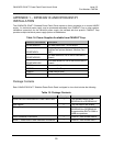
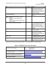
Item Quantity Notes
Metric and English screws 13 Installation requires six screws.
One bag of six metric screws
(M6x1.0x16), one bag of six
English screws (12-24x1/2”), and
an additional screw for the rear
shield are included.
8 inch grounding strap 1 Used to ground the panel to the
frame.
DPoE™ Power Patch Panel Support Tools CD-
ROM containing:
- PANDUIT Element Manager (EM)
software.
- DPoE™ Power Patch Panel Users Guide
(this document)
1
Power connector housing with wire leads 1 This wiring harness is used to
connect the
DPoE™ Power Patch
Panel to the 48VDC power
supply. (Not used if the panel is
powered by an individual power
supply.)
10 Foot Power Harness 1 Used to connect the –48V A-feed
to a power supply.
Butt splices 2 Two butt splices may be used to
extend the 10 Foot Power
Harness. (Do not exceed a total
length of 35 feet).
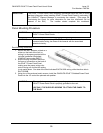
Copper Tape 4 This tape is used to wrap around
the shielded cable foil or braid.
PAN-TY’S
30 The PAN-TY’S are used to secure
the shielded cable to the rear
shield, and secure the shield.
Verify the above contents arrived in good condition. If not, contact
PANDUIT Technical Support.
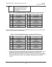
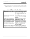
Table 16: PANDUIT Corp Contact Information
PANDUIT Technical Support Fax: 1-708-444-6993
E-mail: cs@panduit.com
For Installation Instructions in Local Languages
and Technical Support
www.panduit.com/resources/install_maintain.asp
Worldwide Subsidiaries and Sales Offices www.panduit.com
Latest Software Updates www.panduit.com/managednetworksolutions