


PANDUIT® DPoE™ Power Patch Panel User’s Guide Issue 2.2
Part Number: PN378A
59
Power Requirements
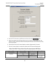
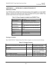
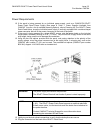
10. If the panel is being powered by an individual power supply, such as a PANDUIT® DPoE™
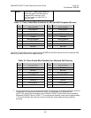
Power Patch Panel Power Supply (See page 8,
Table 1: Power Supplies Available from
PANDUIT Corp for a list of available powering options), skip to Powering Up The DPoE™ Power
Patch Panel below, since the individual power supply is normally equipped with a matched keyed
power connector that will fit the power connector on the back of the panel.
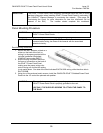
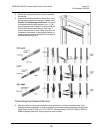
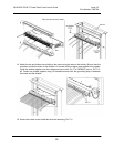
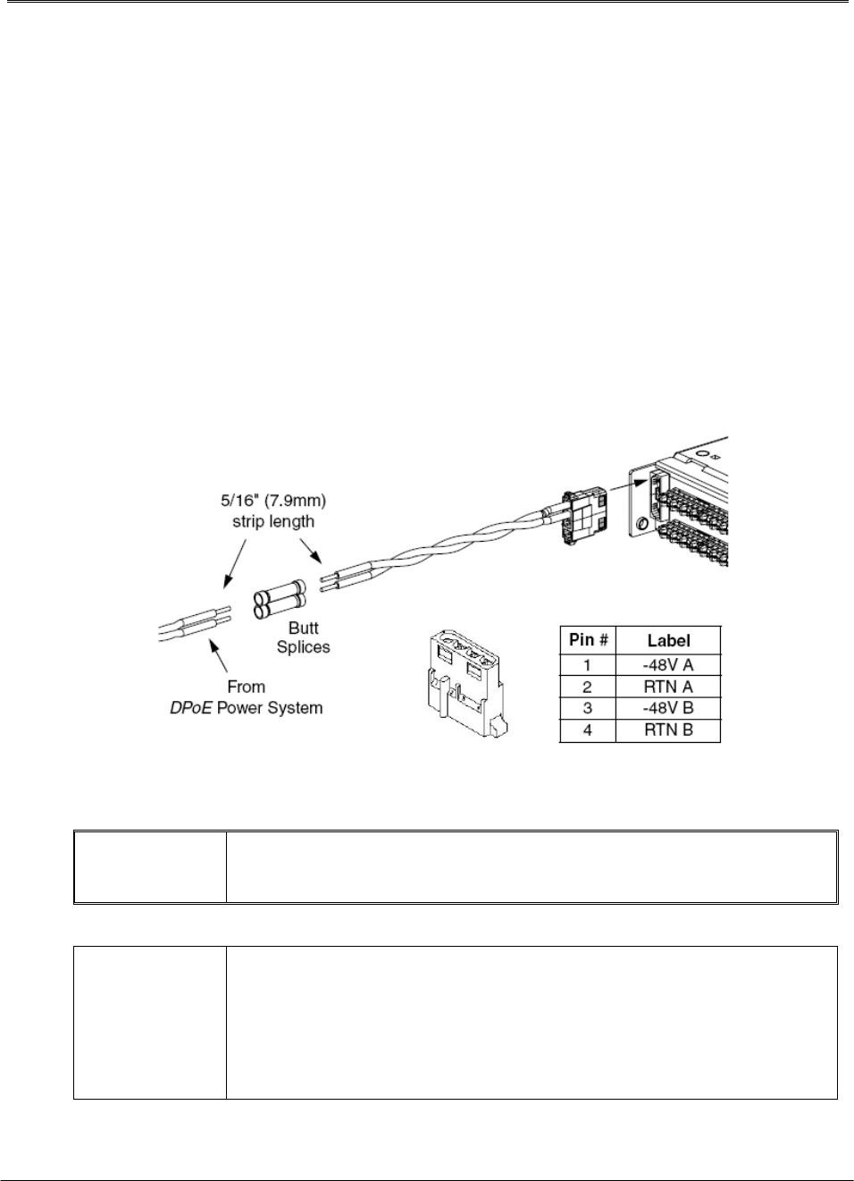
11. If the panel is being powered by a direct 48VDC source, strip the power leads on the included
keyed power connector housing to 5/16” (7.9 mm). Strip the 48VDC supply wires to the same
strip length, being careful not to damage the conductors.
12. Using the two butt splices provided with the panel, and paying attention to the polarity of the
supply voltage, crimp the power harness wires to the supply wires. A crimping tool, such as the
PANDUIT part number CT-100, can be used. The provided butt splices (PANDUIT part number
BSV14X) support 14-16 AWG solid or stranded wire.
WARNING:
The power supply connections are polarized.
The
DPoE™ Power Panel will not function if power is wired improperly.
NOTE:
The included power harness has two wires for the A-feed power only (pins
1 & 2). The
DPoE™ Power Patch Panel supports an optional redundant
B-feed power option, but the terminals and wire leads are not attached to
the power harness.
Contact
PANDUIT Technical Support for more information about
connecting the redundant B-Feed Power.
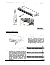
13. Lightly tug on the butt spliced connections to verify that the butt splices are secure.
14. Plug the connector into the back of the
DPoE™ Patch Panel.