


IPD1-A2-GZ40-00 February 2005 15
Connecting Your Subscriber Lines
No configuration is necessary for the interface module(s) installed in your 12000E
to operate at default settings. However, if you wish to run your subscriber
connections at settings other than the defaults, configure the interface module(s)
prior to connection. Refer to the installation instructions for your particular interface
module(s).
The 12000E chassis supports ADSL, IDSL, SDSL and T1/E1 technologies.
Ensure that the subscriber lines you are connecting correspond with the
technology of the interface module(s) installed in your 12000E.
Procedure
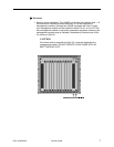
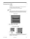
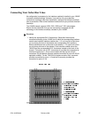
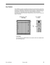
1. Identify the Appropriate RJ21 Connector(s). Subscriber lines must be
connected according to the 12000E slot in which the corresponding interface
module was installed. Interface module slots 1–12 run from left to right when
you are facing the front of the chassis; the corresponding RJ21 ports are
directly behind each slot on the back of the chassis (1–12, right to left, when
you are facing the back of the chassis). Each interface module slot on the
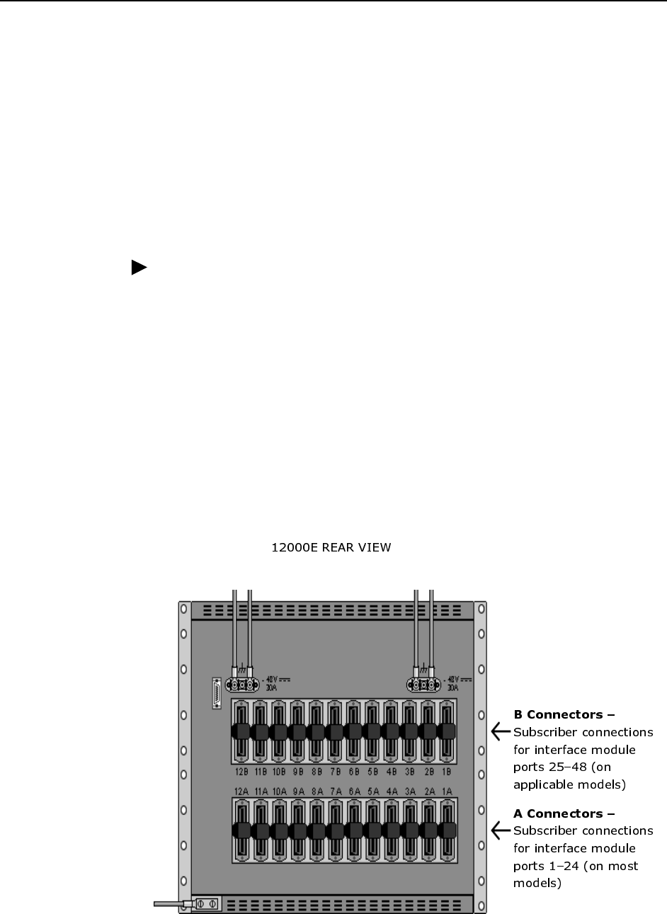
12000E has two corresponding RJ21 connectors located on the back of the
chassis. The bottom row of RJ21 connectors (A) provides the connection for
interface module ports 1–24 (on most models) and the top row of RJ21
connectors (B) provides the interface module connection for ports 25–48 (on
applicable models). For the TIM1500-24 interface module, the A connector
provides connection for ports 1–12 and the B connector provides the
connection for ports 13–24.