16 February 2005 IPD1-A2-GZ40-00
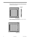
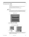
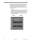
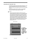
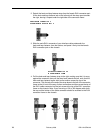
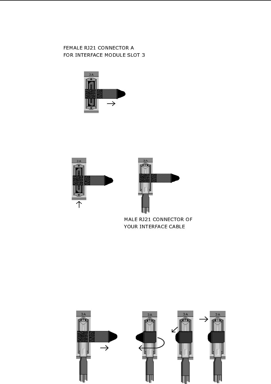
2. Detach the hook-and-loop fastener strap from the female RJ21 connector port:
lift the hook-and-loop fastener tab on the left and pull the strap open towards
the right, leaving it looped under the right side of the connector frame.
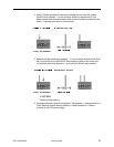
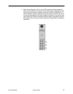
3. Slide the male RJ21 connector of your interface cable underneath the
hook-and-loop fastener, from the bottom, and press it firmly into the female
RJ21 connector port on the chassis.
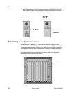
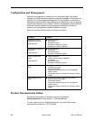
4. Pull the hook-and-loop fastener strap to the right, making sure that it is snug
against the connector, then pull the strap back towards the left, such that the
hook-and-loop fastener layers stick to one another across the top of the
connector. Tuck the tab at the end of the strap down to the left of the connector
frame so that it is out of the way of other connections and then screw the top of
the RJ21 cable connector into the jack screw at the top of the RJ21 connector
frame on the chassis. Note: If you are using a 120 or 180 degree cable, both
the top and the bottom of the cable connector should be screwed to the RJ21
connector frame on the chassis.


