


6 February 2005 IPD1-A2-GZ40-00
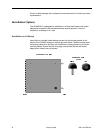
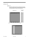
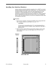
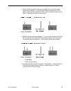
2. Mount the chassis onto the rack and secure the rack mount brackets to the
sides of the rack using one of the two provided sets of eight rack screws
(whichever size fits the rack being utilized).
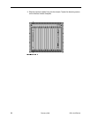
3. Check the rack for stability, ensuring that installation of the 12000E has not
caused the rack to become top-heavy. Position and secure all connecting
cables such that they will not become a tripping hazard or pull loose from the
chassis.
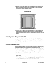
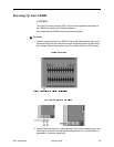
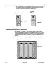
Installing Your Management Module
A management module provides the functional control for the 12000E BLC; the
BLC cannot function without one. There are several different models available for
purchase. Refer to www.paradyne.com for further information, or contact your
sales representative.
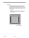
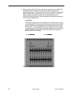
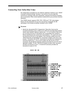
Installing a Management Module
An uplink module provides the upstream network connection for the12000E BLC;
a management module cannot function without one. Depending on the
management module model that you plan to install in your 12000E, you will need
either a Media Interface Module (MIM) or an Uplink Interface Module (UIM). Only
one uplink module is required for operational purposes, however two uplink
modules may be installed, one in each port of the management module, if
redundancy is desired. Refer to your management module and/or uplink module
installation instructions for further information.
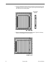
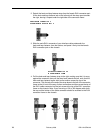
CAUTION:
If a blank plate is removed from a management module uplink port, it must be
replaced with an uplink module. DO NOT OPERATE A 12000E BLC WITH A
MANAGEMENT MODULE THAT HAS AN OPEN UPLINK PORT.