


3-1
3162-A2-GB20-30
March 1999
Operation
3
Overview
This chapter contains information for operating your DSU/CSU. It includes a
description of the front panel LEDs and sample procedures to help you become
familiar with the use of the asynchronous terminal for DSU/CSU control.
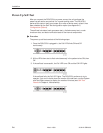
Front Panel LEDs
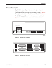
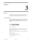
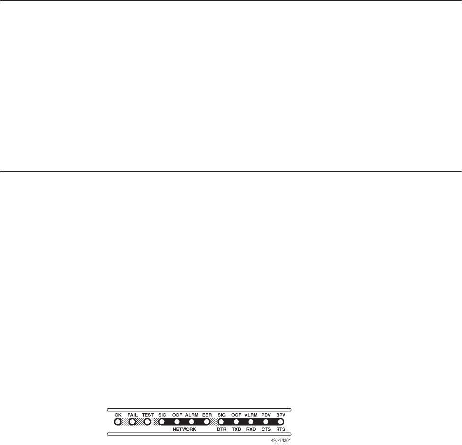
There are twelve LEDs on the DSU/CSU front panel. The five LEDs on the right
(Figure 3-1) are shared between the DTE Drop/Insert (DSX-1) interface and the
data ports. Use the Control branch of the asynchronous terminal menu tree to
choose which port’s status the LEDs display (see
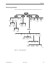
Menu Organization
on
page 3-7).
Figure 3-1. DSU/CSU LEDs
A green LED indicates normal operation. A yellow LED indicates a warning (for
the DTE Drop/Insert interface) or activity (for the data ports). Conditions are
sampled every tenth of a second.
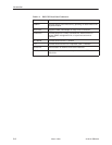
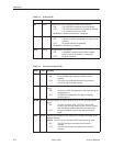
The twelve front panel LEDs are grouped into four sections to indicate the status
of the:
H System (Table 3-1)
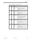
H Network Interface (Table 3-2)
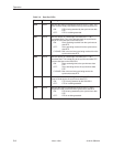
H DTE Drop/Insert (DSX-1) Interface (Table 3-3)
H Data Ports (Table 3-4)