


COMSPHERE 3550 Series Data Service Units
3-4 March 1999 3550-A2-GB20-30
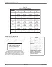
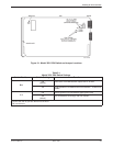
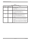
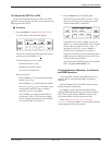
Table 3-2
Model 3551 DSU Jumper Straps
Strap
Designation
State of
Jumper Strap
Function
J12 Left V.35 Test Mode Indication:
Left — Enables V.35 Test Mode Indication (Pins 1 and 2).
This is
the factory default.
Right — Disables V.35 Test Mode Indication (Pins 2 and 3).
J13 Left EIA-232-D Test Mode Indication:
Left
— Enables EIA-232-D Test Mode Indication
(Pins 1 and 2).
This is the factory default.
Right — Disables EIA-232-D Test Mode Indication
(Pins 2 and 3).
J20 Left Alarm Monitoring (used with the –48 Vdc Central Office Power Unit):
Left — Disables the –48 Vdc alarm monitoring function
(Pins 1 and 2).
This is the factory default.
Right — Enables the –48 Vdc alarm monitoring function
(Pins 2 and 3); the NMS adapter cable is being used for alarm
monitoring.
J21 Right Alarm Monitoring (used with the –48 Vdc Central Office Power Unit):
Left — Enables control of alarm monitoring via the NMS adapter
cable (Pins 1 and 2); the NMS adapter cable is being used for alarm
monitoring.
Right — Disables control of alarm monitoring via the NMS adapter
cable (Pins 2 and 3); a standard EIA-232 cable or the NMS adapter
cable is being used for the diagnostic channel.
This is the factory
default.