


Operating the DSU
4-33550-A2-GB20-30 March 1999
Select
SDU12345678910111213141516
SELECT
KEY
STATUS
INDICATORS
CARRIER SLOTS 1–16
F1 F2 F3
OK Alarm BckUp Test EC
NETWORK
DEVICE
ALARM
DIAL
BACKUP
TEST
MODE
ERROR
CORRECTION
OK Alarm BckUpTest EC
KEYPAD
LCD DISPLAY
TXD
RXD
RTS
CTS
DSR
DTR
LSD
103
104
105
106
107
108
109
OK
Alrm
Test
Dial
Status
Front Panel
NETWORK/
DEVICE ALARM
TEST MODE
DIAL BACKUP
DTE
STATUS
INDICATORS
SDCP
INDICATOR
Multirate
DSU
3551
496-14463-01
COMSPHERE 3000
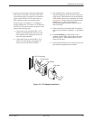
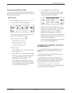
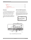
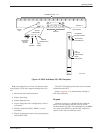
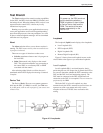
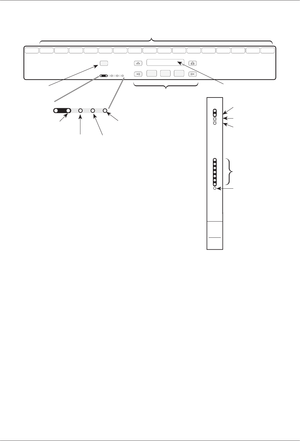
Figure 4-2. SDCP and Model 3551 DSU Faceplate
Both control panels have a 2-line, 16-character liquid
crystal display (LCD) and a keypad, through which you
can
• Monitor the unit’s health and status
• Initiate dial backup
• Initiate diagnostic tests
• Load or change the unit’s configuration, or how it
will operate
• Enable or disable the DSU’s, DBM’s, or port’s
transmitter
• Display or change the status of the general purpose
external DTE leads.
The DCP’s LCD displays the result of any command
initiated from the DCP.
Refer to Appendix C to understand the meaning of
DCP status indicators.
Keypad
There are seven keys on the DCP of the standalone
Model 3550, and eight on the SDCP for the carrier-
mounted Model 3551 DSU. The additional key, the Select
key, connects the SDCP to a specific DSU located in a
specific carrier and slot within the carrier.