


Installing the Model 3551 DSU
3-93550-A2-GB20-30 March 1999
Connecting to the
DDS (or LADS) Network
NOTE
Before connecting the DSU to
the DDS network, ensure that
approved primary protectors
have been installed on the
circuit in accordance with Article
800 of the National Electric
Code, NFPA 70, in the United
States and Section 60 of the
Canadian Electric Code, Part 1,
in Canada.
If connecting the DSU to a LADS network there are
distance limitations that govern the use of DSUs on the
network. Table 2-2 in Chapter 2 summarizes these
limitations.
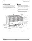
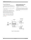
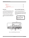
The DDS network interface is provided by two RJ48T
50-pin connectors on the back of the carrier (refer back to
Figure 3-2, DDS Interface). Each connector serves eight
contiguous slots in the carrier: one for Slots 1 through 8
and one for Slots 9 through 16.
Appendix E provides connectivity diagrams should
you need further assistance in connecting the DSU to the
network.
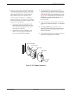
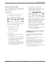
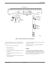
Connecting the DSU to a DTE
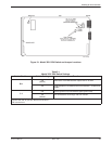
The DTE interface for the Model 3551 DSU is
provided through its rear connector plate. Each rear
connector plate contains two DB25 (or 25-pin D-type)
connectors. The top connector is an EIA-232-D/V.24
(ISO 2110) connector. The bottom connector is a ITU-T
V.35 (ISO 2593) connector.
To use the 25-pin V.35 connector (used for speeds
greater than 19.2 kbps), a V.35 adapter is needed (feature
number 3000-F1-510). This adapter provides the interface
between the 25-pin V.35 D-type connector and a V.35
DTE cable.
Each DSU can be configured to use either interface
(EIA-232 or V.35) independent of other DSUs in the
carrier. Connection of the DSU to the DTE is a matter of
selecting and installing the appropriate cable. Refer to the
COMSPHERE 3000 Series Carrier, Installation Manual
for installation procedures.
Appendix E provides connectivity diagrams should
you need further assistance in connecting the DSU to the
network.
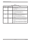
Addressing the Unit
A unique address must be assigned to each control and
tributary DSU in your network. You can assign an address
within the range of 1 through 255.
NOTE
Do not assign the number 192
as a network address. This
number is reserved as a
broadcast address.
If a DBM is installed, it requires a separate address
which is automatically assigned by the DSU. The address
assigned a DBM is the DSU’s address, plus 1 (e.g., if the
DSU’s address is 1, the assigned DBM address will be 2).
NOTE
The numbers 191 and 255
cannot be assigned to a DSU
that has a DBM. However,
addresses can be assigned in
any order; they do not have to be
sequential.
It is recommended that only
odd-numbered addresses
be
assigned to DSUs so that
even-numbered addresses
are
reserved for DBMs
.
If your
network does not currently
include DBMs, you retain the
flexibility to add them later
without having to reconfigure
your entire network.