Configuring the Unit
5-193550-A2-GB20-20 December 1996
Table 5-8
(3 of 4)
General Configuration Options
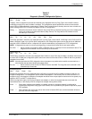
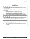
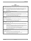
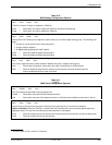
LL by DTE: Disab
Next Enab Disab Prev
Local Loopback by DTE
(only displayed when Full Mode is enabled). Controls the use of Pin 18 of the EIA-232-D/V.24
interface or Pin L of the V.35 interface by the DTE to initiate a Local Loopback when the DSU is the active device.
Whenever this lead is ON, the Local Loopback overrides any other diagnostic tests run by the network.
Enab — Select if the DTE is to signal the DSU to perform a Local Loopback. Local Loopback ends when the
signal is dropped.
Disab — Select if Local Loopback requests are to be ignored.
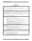
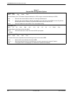
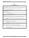
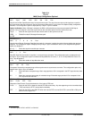
RL by DTE: Disab
Next Enab Disab Prev
Remote Digital Loopback by DTE
(only displayed when Full Mode is enabled). Allows the DTE to initiate a Remote
Digital Loopback via Pin 21 of the EIA-232-D/V.24 interface or Pin N of the V.35 interface.
Enab — Select if the DTE is to force the DSU to request a Remote Digital Loopback when the signal is turned ON.
Remote Digital Loopback ends when the signal is dropped.
Disab — Select if the DSU is to ignore requests for a Remote Digital Loopback.
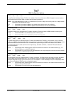
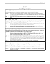
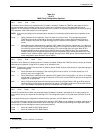
Bilat Lpbk:Disab
Next Enab Disab Prev
Bilateral Loopback
(only displayed when Full Mode is enabled). If this configuration option is enabled, a DTE Loopback
occurs when a Digital Loopback occurs.
Enab — Select for a DTE Loopback to be run whenever a Digital Loopback occurs.
Disab — Select for the DSU to ignore requests for a Bilateral Loopback.
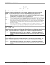
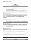
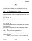
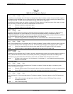
Ext Leads: Rate
Next ExtLd Rate RPowr Prev
External Leads
(only displayed when Full Mode is enabled). Controls the use of the general-purpose leads on the
EIA-232-D/V.24 interface for Port 1, except when Rate is selected. These leads can be controlled and monitored from
the DCP or from a 6700 Series NMS.
ExtLd — Select to enable Pin 12 and 13 as output (control) and Pins 19 and 23 as input (alarm) leads. When
enabled, Pins 12 and 13 output +12V when ON and –12V when Off. Pins 19 and 23 recognize voltages
from +2.2V to +12V as ON (reported as an external alarm) and –12V to +.8V as Off.
Rate — Select if a TDM/Flex is installed, so that Pin 12 on each port can be used to control speed selection and
cause an extended modem to change speed to match the backup port speed.
RPowr — Select only when a redundant power supply is installed in the COMSPHEREr 3000 Series Carrier. This
selection functions similarly to ExtLd.
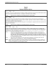
CCN by EL: Disab
Next Enab Disab Prev
Configuration Change Notification by External Leads
(only displayed when Full Mode is enabled). Controls the use of the
general-purpose output leads to set a CCN event.
Ext Leads
must be set to ExtLd.
Enab — Select if a change in state of a general-purpose lead signals CCN to the NMS.
Disab — Select if changes to the lead state do not set a CCN event.


