3. Configuration Options
3-78 December 2002 9000-A2-GB31-00
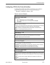
Configuring Node IP Information
Select Node IP to display, add, or change the information necessary to support
general IP communications for the node (see Table 3-31, Node IP Options). When
deploying units to remote sites, minimally configure the Node IP Address and
Subnet Mask.
Main Menu
→Configuration→Management and Communication→Node IP
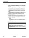
This set of configuration options includes a Troubleshooting (TS) Management
Access Link feature to help service providers isolate device problems within their
networks. This feature allows Telnet or FTP access to the unit on this link.
Troubleshooting over this link is essentially transparent to customer operations.
No alarms or SNMP traps are generated to create nuisance alarms for the
customer.
TS_Access_Management_Link is initially disabled in most models, but the link can
be enabled at any time. Any valid network Management PVC created on a
standard DLCI can be used. When enabled, a troubleshooting link can be
accessed any time the service provider requests access. An assigned security
level can also control access.
When a DLCI has been defined as the troubleshooting management link, the link
is identified in the status field at the bottom of the Management PVC Entry screen
with the Note: This PVC has been designated as the TS Access
Management Link message.
NOTE:
The unit may come from the factory with a TS Management PVC already set
up (e.g., 980).
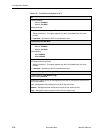
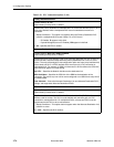
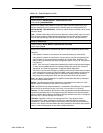
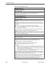
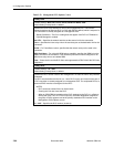
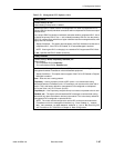
Table 3-31. Node IP Options (1 of 4)
Node IP Address
Possible Settings: 001.000.000.000 – 223.255.255.255, Clear
Default Setting: Clear (000.000.000.000)
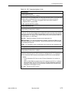
Specifies the IP address needed to access the node. Since an IP address is not bound to
a particular port, it can be used for remote access via a management PVC.
001.000.000.000 – 223.255.255.255 – Shows the IP address for the node, which can be
viewed or edited.
Clear – Fills the node IP address with zeros.


