3. Configuration Options
9000-A2-GB31-00 December 2002
3-31
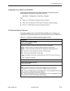
Configuring a User Data Port (CSU/DSUs)
Select Physical from the Data Ports menu to display or change the physical
characteristics of the data port connected to the DTE.
Main Menu→Configuration→Data Ports→Physical
See:
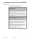
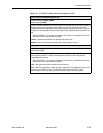
n Table 3-15, V.35 Data Port Physical Interface Options
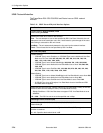
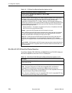
n Table 3-16, EIA-530-A/X.21/V.35 Data Port Physical Interface Options
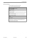
n Table 3-17, HSSI Data Port Physical Interface Options
V.35 Data Port Physical Interface
FrameSaver Models 9123, 9126, 9623, 9626, and 9783 have a V.35 data port.
The Model 9128 standalone and carrier-mounted units have two V.35 data ports.
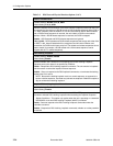
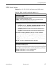
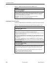
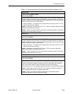
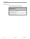
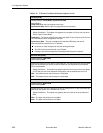
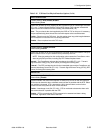
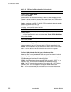
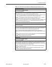
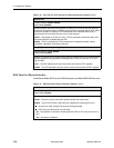
Table 3-15. V.35 Data Port Physical Interface Options (1 of 6)
Port Status
Possible Settings: Enable, Disable
Default Setting: Enable
Determines whether the data port is being used and can be configured.
Enable – The port is active, and can be used to transmit and receive data.
Disable – The port is not active. When the port is disabled, the following will occur:
No alarms or traps configured for the port will be generated.
LED for the port will be held in an Off state.
No – The operation is canceled. (Pressing either the Esc or Ctrl-a key also acts as a
No.)
Yes – Port status is disabled.
Port Type (9788, 9820-2M, 9820-8M)
Possible Settings: E530, V.35, X.21
Default Setting: V.35
Specifies the port type of the data port.
E530 – The port is configured as an EIA-530-A-compatible DCE. An EIA-530-A-
compatible DTE may be directly connected to the DB25 connector for the port.
V.35 – The port is configured as a V.35-compatible DCE. A V.35-compatible DTE may be
connected to the port using a DB25-to-MS34 adapter.
X.21 – The port is configured as an X.21-compatible DCE. An X.21-compatible DTE may
be connected to the port using a DB25-to-DB15 adapter.


