


E-1
9161-A2-GH30-30
April 1998
Cables, Connectors, and Pin
Assignments
E
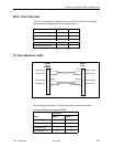
COM Port
The COM (communications) port connects to an async terminal or other
management interface.
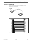
These cables are:
H 14-foot, 26 AWG, 8-conductor, with a non-keyed 8-position modular jack
interface/connector at one end, and
H 25-pin or 9-pin connector at the other end, depending upon the management
interface used.
Refer to the appropriate cable section.
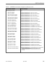
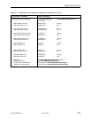
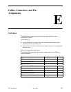
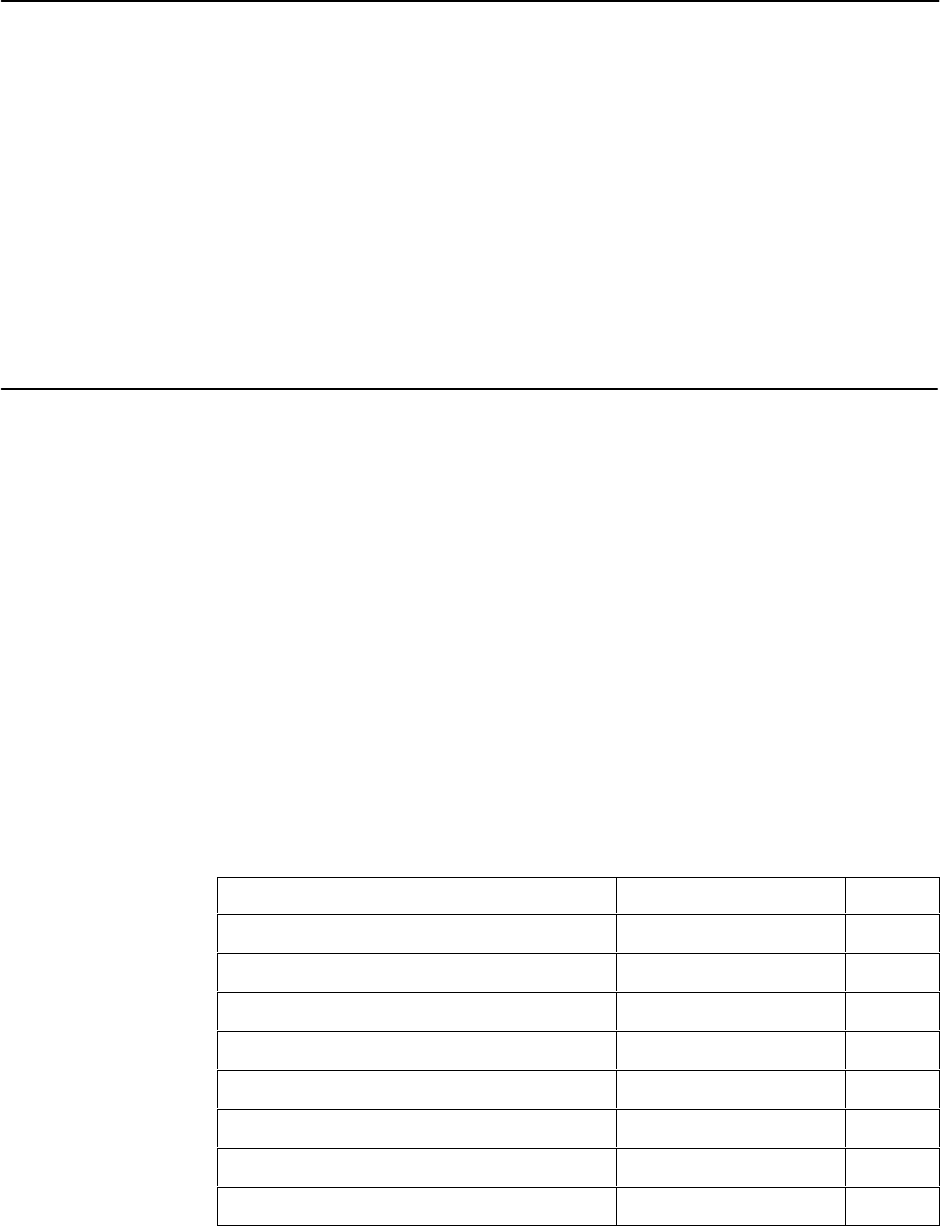
The following table shows the signals and pin assignments for the COM port
interface/connector.
Signal
Direction Pin #
DCE Transmit Clock (TXC) Out 1
DCE Received Data (RXD) Out 2
Signal Ground (SG) — 3
DCE Transmit Data (TXD) In 4
DCE Data Terminal Ready (DTR) In 5
DCE Carrier Detect (CD) Out 6
DCE Request to Send (RTS) In 7
DCE Received Clock (RXC) Out 8