Connectors, Cables, and Pin Assignments
C-3
9820-A2-GB20-20
June 2000
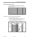
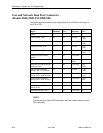
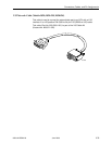
COM (Terminal) Port Connector
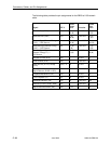
The following table shows the signals and pin assignments for the DB25
communication port connector. The communication port is called the Terminal
port on the Model 9820-45M.
Signal
Direction Pin #
Shield — 1
Transmit Data (TXD) To COM port (In) 2
Received Data (RXD) From COM port (Out) 3
Request to Send (RTS) To COM port (In) 4
Carrier Detect (CD) From COM port (Out) 5, 6, 8
Signal Ground (SG) To/From COM port 7
Data Terminal Ready (DTR) To COM port (In) 20
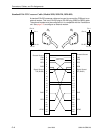
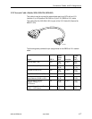
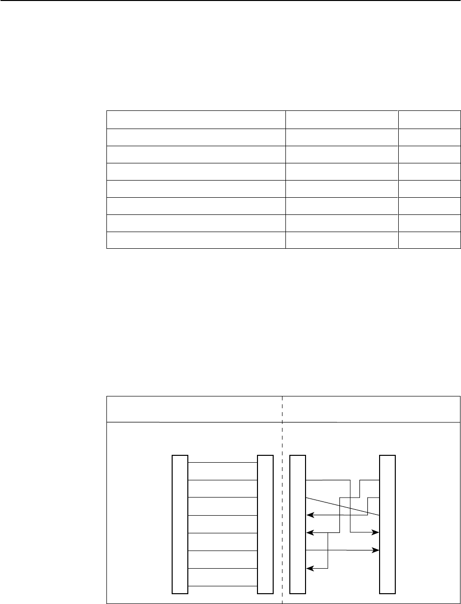
LAN Adapter Converter and Cable (Models 9820, 9820-2M, 9820-8M)
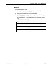
The following shows the pin assignments for the:
H DB25 plug-to-modular jack converter between the COM (Terminal) port and
the 8-conductor LAN Adapter cable (Feature No. 3100-F1-920)
H Custom 8-conductor cable (with modular plugs on both ends) between the
converter and the LAN Adapter (Feature No. 3100-F2-910)
Unused
DTR
Tx Data
Signal Ground
Rx Data
CTS
Frame Ground
Unused
Plug to
Modular Jack
Plug to
LAN Adapter
98-16214
1
2
3
4
5
6
7
8
1
2
3
4
5
6
7
8
Tx Clock
Rx Data
Signal Ground
Tx Data
DTR
CD
RTS
Rx Clock
Com Port
(DB25 Plug)
8-Position
Modular Jack
15
3
7
2
20
8
4
17
1
2
3
4
5
6
7
8
Plug-to-Modular
Jack Converter
Cable


