


19
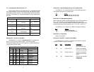
The Model 1092A Test Modes are described on the following page.
To run or terminate a particular test, key in the option to get to that
screen menu.
OFF Terminates all tests
511 Initiates the built-in test pattern generator
and detector.
511 with Errors Initiates the built-in test pattern generator
and detector. The test pattern generator
also injects intentional errors approximately
once per second.
Local Line Loop Initiates the Local Line Loop test and starts
and 511 the internal 511 generator and detector.
Local Line Loop Initiates the Local Line Loop test and starts
and 511 w/errorsthe internal 511 generator and detector. In
this test, the 511 pattern generator injects
intentional errors into the data stream.
Remote Digital Initiates the Remote Digital Loopback test.
Loop Any data sent to the remote 1092A is
returned to the originating device.
Remote Digital Initiates the Remote Digital Loopback test
Loop and 511 and starts the internal 511 generator and
detectors.
Remote Digital Initiates the Remote Digital Loopback test
Loop and and starts the 511test patterns. In this test
511 with errors the 511 pattern generator will inject initial
errors into the data stream.
The Modem Status Screen is displayed upon initiating a test.
Press ‘ESC’ to return to the Test Mode Menu.
Press the space bar to update and redisplay the status.
20
4.0 INSTALLATION
Once the Model 1092A is properly configured, it is ready to
connect to the twisted pair interface, to the serial port, and to the power
source. This section tells you how to make these connections.
4.1CONNECTING THE TWISTED PAIR INTERFACE
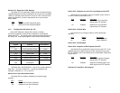
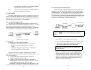
The Model 1092A supports communication between two DTE
devices at distances to 5 miles (8 km) over 24AWG (.5mm) twisted pair
wire. There are two essential requirements for installing the Model
1092:
1. These units work in pairs. Both units at the end of the twisted
pair must have the same 2-Wire or 4-Wire setting. For
instance, if the application is a 2-Wire application, then both
units must be in the 2-Wire setting.
2. To function properly, the Model 1092A needs one or two
twistedpairs of metallic wire. This twisted pair must be
unconditioned, dry, metallic wire, between 19 (.9mm) and 26
AWG (.4mm) (the higher number gauges may limit distance
somewhat). Standard dial-up telephone circuits, or leased
circuits that run through signal equalization equipment, or
standard, flat modular telephone type cable, are not
acceptable.
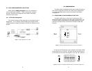
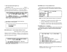
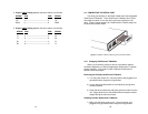
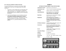
The RJ-45 connector on the Model 1092A’s twisted pair interface is
polarity insensitive and is wired for a two-wire or four-wire interface.
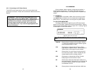
The signal/pin relationships are shown in Figure 4 below.
Figure 4.Model 1092A twisted pair lineinterface.
1 (N/C)
2 (GND)
3 (4-Wire Rx)
4 (2-Wire TIP/4-Wire Tx)
5 (2-Wire RING/4-Wire Tx)
6 (4-Wire Rx)
7 (GND)
8 (N/C)
1
2
3
4
5
6
7
8