


7
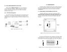
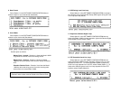
3.1.1 Configuration DIP Switch Set “S1”
Use the eight switches in DIP Switch Set “S1” to configure the data
rate, asynchronous or synchronous data format, transmit clock source
and response to RDL request. The following table summarizes default
positions of DIP Switch S1. Detailed descriptions of each switch follow
the table.
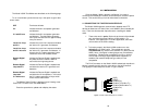
Switches S1-1 and S1-2: Data Rate
Use Switches S1-1 and S1-2 with Switch S2-1to configure the
Async or Sync bit rate for Model 1092A. The following table
summarizes default positions of DIP Switch S2. Detailed descriptions
of each switch follow the table.
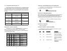
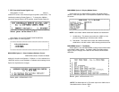
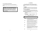
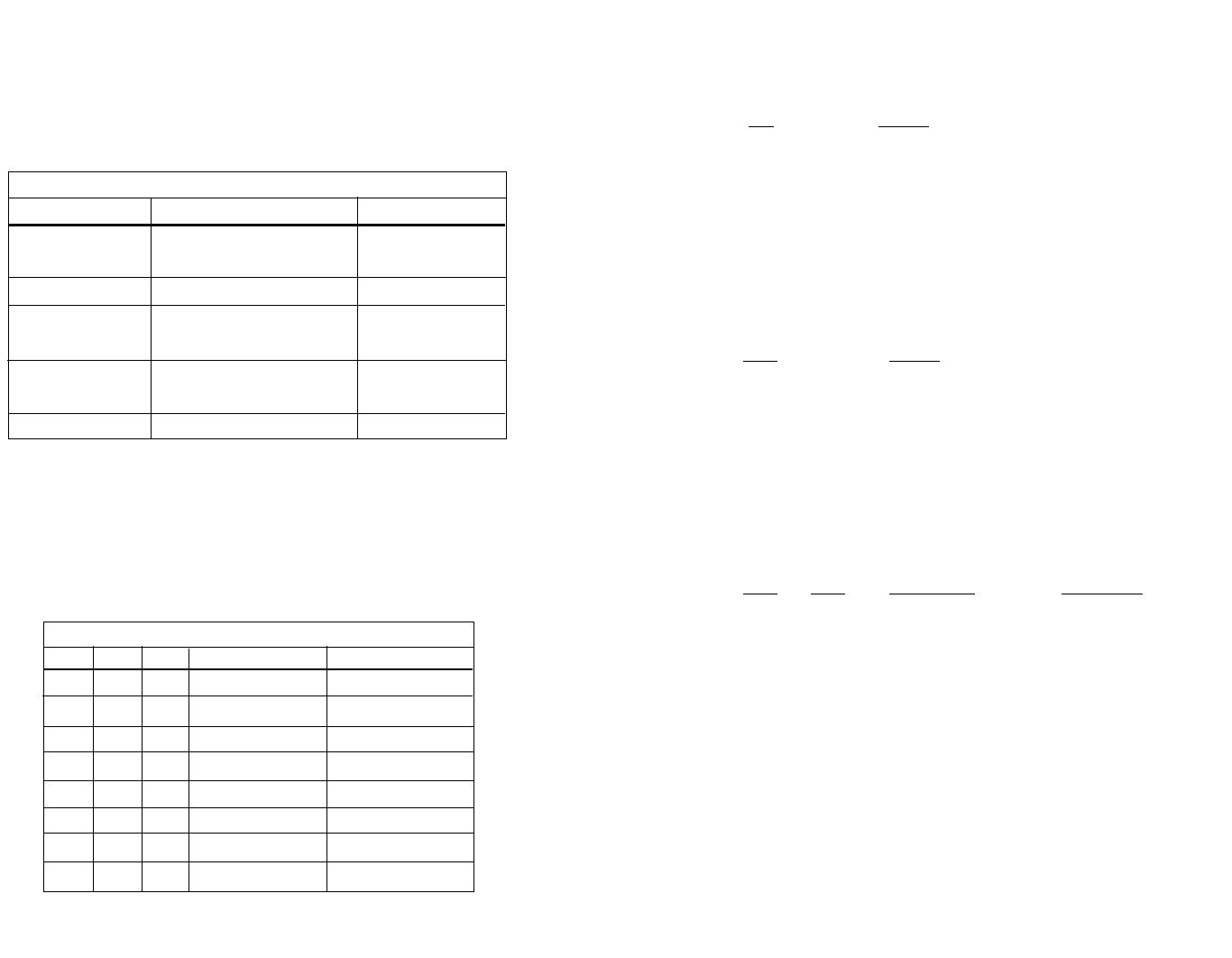
S1 SUMMARY TABLE
Position Function Factory Default
S1-1 Data Rate On
S1-2 Data Rate Off
S1-3 DSR during Local Line LoopOn DSR On
S1-4 SNMP Management Off VT100 Mgmt
S1-5 Reserved Off
S1-6 Tx Clock Source On
S1-7 Tx Clock Source On
S1-8 Response to RDLRequestOn Enable
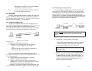
64K Sync
}
}
Internal Clock
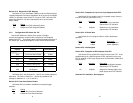
S1-1S1-2S2-1Sync Data RateAsync Data Rate
OnOnOff 32 kbps Reserved
OffOnOff 56 kbps Reserved
OnOffOff 64 kbps Reserved
OffOffOff 128 kbps 0-38.4 kbps
OnONOn Reserved Reserved
OffOnOn Reserved Reserved
OnOffOn Reserved Reserved
OffOffOn 19.2 kbps Reserved
Possible Bit Rate Settings - Switch S1-1, S1-2 and S2-1
8
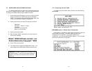
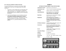
Switch S1-3: Data Set Ready During Line Loopback Test
Use Switch S1-3 to control the behavior of the DSR signal at the
EIA interface during the line loopback test.
S-3 Setting
On DSR is on during local line loop
Off DSR is off during local line loop
Switches S1-4: Management Setting
When setting the 1092A to SNMP Management, the DTE rate switches
(S1-1, S1-2, and S2-1) are also needed to be at the ONposition.
Therefore, to set a 1092A unit SNMP management mode, the following
switches have to be at the ON position, S1-1, S1-2, S2-1, and S1-4.
Use Switch S1-4 to configure the 1092A’s management setting.
S1-4 Setting
On SNMP Management
Off Control Port Management
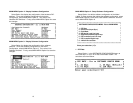
Switches S1-5: Reserved
Always at off position
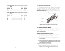
Switches S1-6 and S1-7: System Clock Mode
Use Switches S1-6 and S1-7 to configure the 1092A for internal,
external, or receive recover clock mode.
S1-6S1-7 Clock Mode Description
On On Internal System clock
generated internally
Off On External (DTE) System clock derived
from terminal interface
On Off Receive Recover System clock derived
from the received line
signal.
Off Off Hardware Reset Reset to use hardware
switches for
configuration