


25
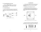
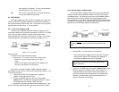
4.3.2 Connecting to a DC Power Source
The 48 VDC power supply option uses a 3-pin terminal block with
spring-type connectors. Please refer to the Model 1090 Series Service
Manual.
WARNING!There are no user-serviceable parts in the
power supply section of the Model 1092A.Voltage setting
changes and fuse replacement should only be performed by
qualified service personnel. Contact Patton Electronics
Technical support at
(301)975-1007
, via our web site at
http://www.patton.com, or by e-mail at support@patton.com,
for more information.
5.0 OPERATION
Once the Model 1092A is properly configured and installed, it
should operate transparently. This sections describes power-up,
reading the LED status monitors, and using the built-in loopback test
modes.
5.1 POWER-UP
To apply power to the Model 1092A, first be sure that you have
read Section 4.3, and that the unit is connected to the appropriate
power source. Then power-up the unit using the rear power switch.
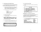
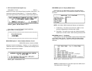
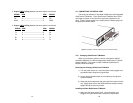
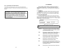
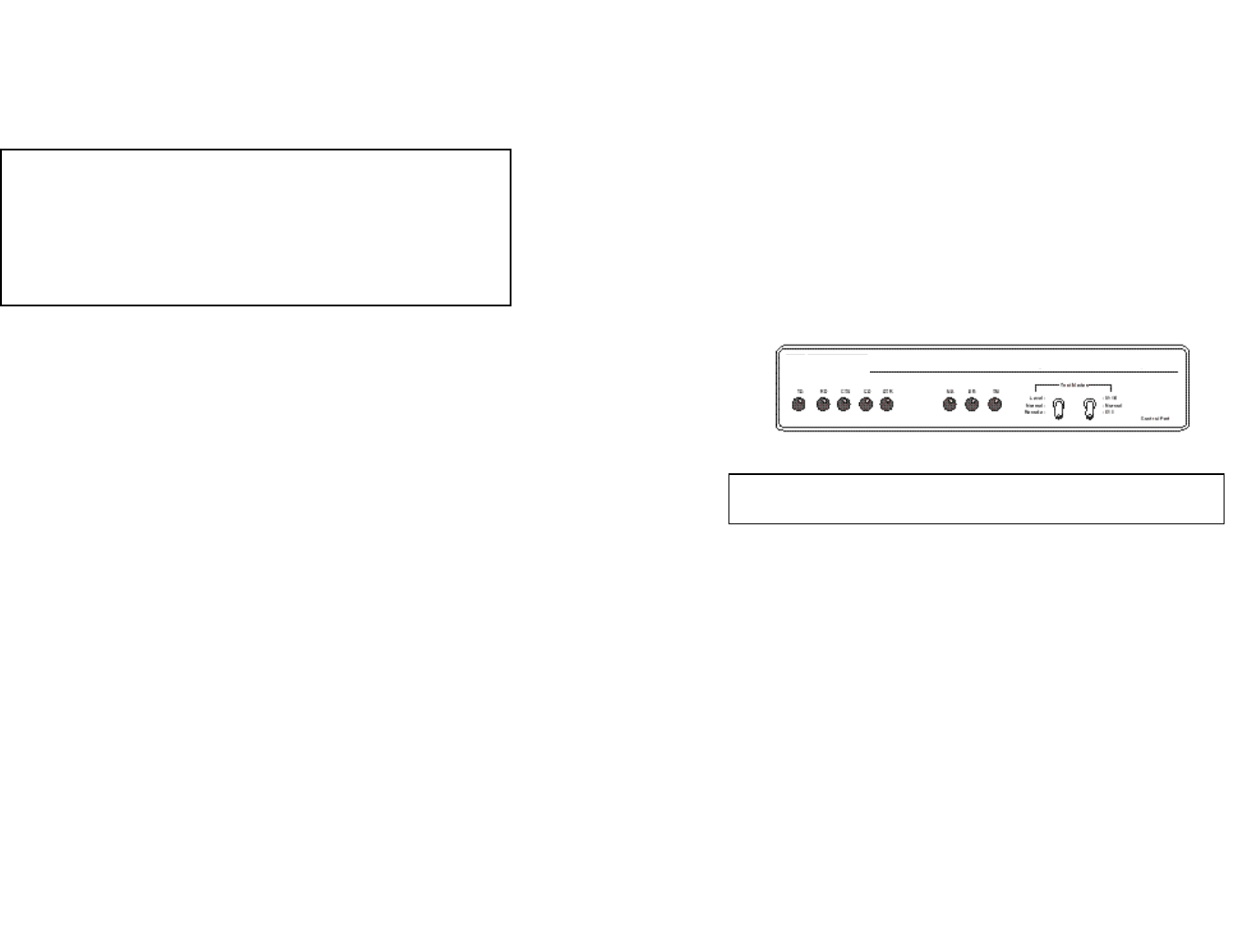
5.2 LED STATUS MONITORS
The Model 1092A features eight front panel LEDs that monitor
power, the DTE signals, network connection and test modes. Figure 6
(below) shows the front panel location of each LED. Following Figure 6
is a description of each LEDs function.
TD & RDGlows yellow to indicate an idle condition of Binary
“1” data on the respective terminal interface signals.
Green indicates Binary “0” data.
CTS Glows green to indicate that the Clear to Send
signal from the modem is active. Yellow indicates an
inactive Clear to Send signal from the modem.
CD Glows yellow if no carrier signal is being received
from the remote modem. Green indicates that the
remote modem’s carrier is being received.
DTR Glows green to indicate that the Data Terminal
Ready signal from the terminal is active.
ER Glows red to indicate the likelihood of a Bit Error in
the received signal. During the 511 or 511/E test, ER
will flash to indicate that the Test Pattern Detector
has detected a bit error.
TM Glows yellow to indicate that the Model 1092A has
Figure 6.Model 1092A Front Panel
26
Note: LEDs described as yellow are red in earlier versions of the
1092A.