


15
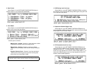
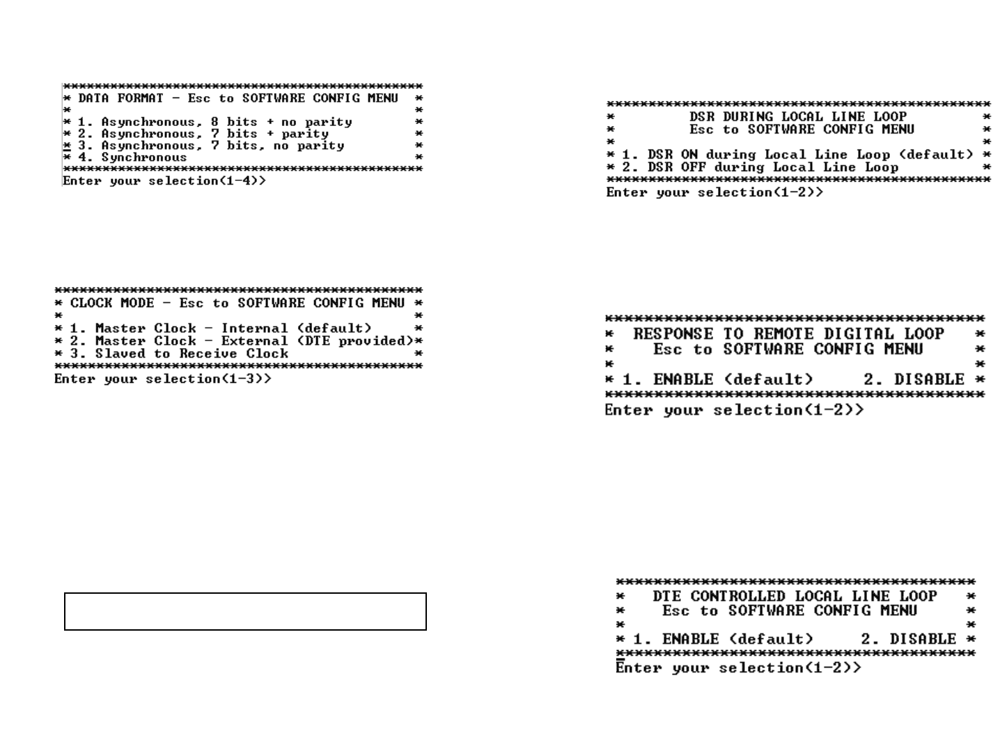
2. Data Format
Select Option 2 in the SOFTWARE CONFIGURATIONMenu to
select the async or sync data format (See below).
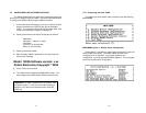
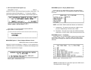
3. Clock Mode
Select Option 3 in the SOFTWARE CONFIGURATION Menu to
select the sync clock mode (See below).
Set this option as follows:
Master Clock - Internal: Selection 1 allows the Model 1092A
to generate an internal clock as the timing source.
Master Clock - External: Selection 2 allows the Model
1092A to Derive the system clock from the locally connected
DTE.
Slaved to Receive Clock:Selection 3 to allows the Model
1092A to derive the timing source from the incoming data
stream from the remote Model 1092A.
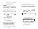
Important: One 1092A must be a Master Clock (either internal
or external) and the other must be Slaved to the Receive Clock.
16
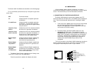
4. DSR During Local Line Loop
Select Option 4 in the SOFTWARE CONFIGURATION to configure
the behavior of the local Data Set Ready (DSR) signal during the Local
Line Loop test mode (below).
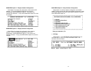
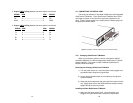
5. Response to Remote Digital Loop
Select Option 5 in the SOFTWARE CONFIGURATION Menu to
instruct the Model 1092A to either respond or ignore the Remote Digital
Loop request from the remote 1092A.
6. DTE Controlled Local Line Loop
Select Option 6 in the SOFTWARE CONFIGURATIONMenu to
instruct the Model 1092A to either respond or ignore Local Line Loop
requests from the DTE. To instruct the Model 1092A to respond to
Local Line Loop requests from the DTE, select Enable (Option 1). To
instruct the 1092A to ignore Local Line Loop requests from the DTE
interface, select Disable (Option 2).