


CopperLink 1214E Front Panel 15
CopperLink 1214E User Manual 1 • General Information
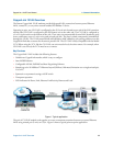
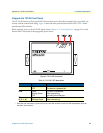
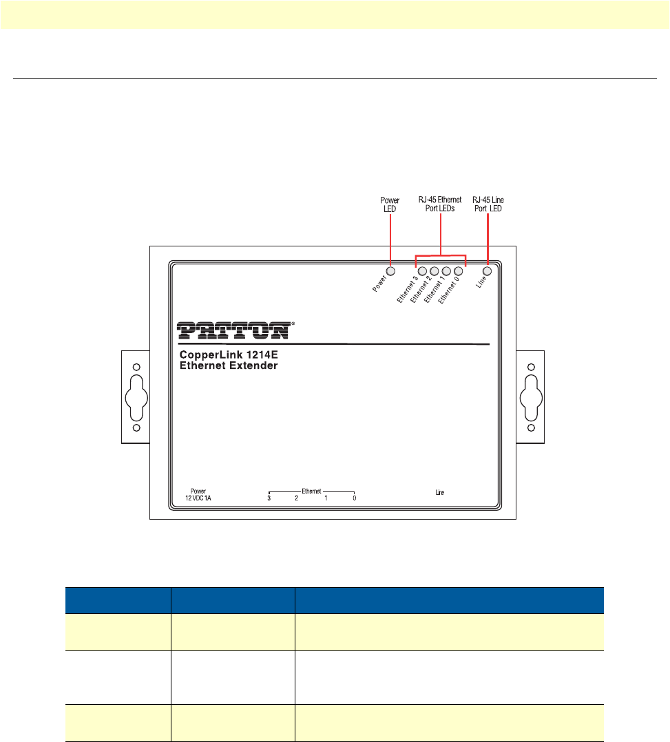
CopperLink 1214E Front Panel
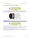
The CL1214E features six front panel LEDs that monitor power, the Ethernet signals, the CopperLink con-
nection, and the remote/local setting. Figure 2 shows the front panel location of each LED. Table 2 below
describes the LED functions.
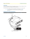
Before applying power to the CL1214E, please review Chapter 2, “Connecting Power” on
page 19 to verify
that the unit is connected to the appropriate power source.
Figure 2. CL1214E front panel
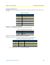
Table 2. CL1214E LED description
LED Indication Description
Power Green
OFF
The device is powered on.
The device is powered off.
Link Green
Blinking Green
OFF
The port is connected.
Data transceiving.
No valid link on this port.
Ethernet
(3, 2, 1, 0)
Green
*Blinking Green
The port is connected.
Data transceiving.
* Once the unit connects to a power source, the Link LED will blink as the CL1214E automatically looks for
the other unit in the pair.