


Connecting the 10/100Base-T Ethernet Interface 19
CopperLink 1214E User Manual 2 • Installing the CL1214E
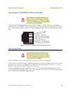
Connecting the 10/100Base-T Ethernet Interface
CAUTION
The Interconnecting cables shall be accept-
able for external use and shall be rated for
the
proper application with respect to voltage,
current, anticipated temperature, flammability,
and mechanical serviceability.
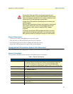
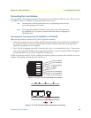
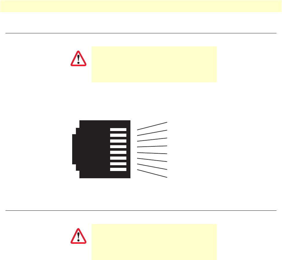
The RJ-45 ports labeled Ethernet are the Auto-MDIX10/100Base-T interface. These ports are designed to
connect directly to a 10/100Base-T device or network. Figure 6 shows the signal/pin relationships on this inter-
face. You may connect this port to a hub or PC using a straig
ht through or crossover cable that is up to 328 ft
long.
1 TX+/RX+
2 TX-/RX-
3 RX+/TX+
4 (no connection)
5 (no connection)
6 RX-/TX-
7 (no connection)
8 (no connection)
1
2
3
4
5
6
7
8
Figure 6. CL1214E 10/100Base-T RJ-45 Connector Pin-out
Connecting Power
CAUTION
The Interconnecting cables shall be accept-
able for external use and shall be rated for
the
proper application with respect to voltage,
current, anticipated temperature, flammability,
and mechanical serviceability.
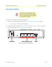
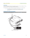
The CL1214E does not have a power switch, so it powers up as soon as it is plugged in.
An external AC or DC power supply is available separatel
y. This connection is made via the barrel jack on the
rear panel of the CL1214E. No configuration is necessary for the power supply (See Appendix C on page 31
for domestic and international power supply and cord options).
DC power (supplied via the power supply jack to the 12
14E) must meet the following requirements; DC
power supplied must be regulated 12VDC ±5%, 1.0A minimum. Center pin is +12V. The barrel type plug has
a 2.5/5.5/10mm I.D./O.D./Shaft Length dimensions.