


Introduction 21
CopperLink 1214E User Manual 3 • Configuration and Operation
Introduction
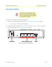
The CL1214E has eight DIP switches (S1) for configuring the unit for a wide variety of applications. This sec-
tion describes switch locations and explains the different configurations.
Once the CL1214E’s are properly installed, they should
operate transparently. No user settings required.
Note Before applying power to the CL1214E, please review Chapter 2, “Connect-
ing Power” on page 19 to verify that the unit is connected to the appropriate
power source.
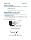
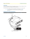
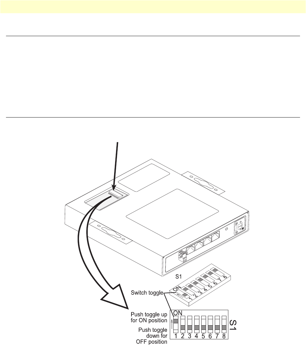
Configuring the Hardware DIP Switches
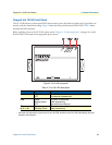
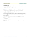
The DIP switches are externally accessible from the underside of the CL1214E. Figure 7 shows the orientation
of the DIP switches in the On and Off positions.
Figure 7. DIP switch orientation