


Connecting the Line Interface 18
CopperLink 1214E User Manual 2 • Installing the CL1214E
Connecting the Line Interface
The CopperLink 1214E supports communication between two peer Ethernet LAN sites over a distance of up
to 10,000 ft (3 km) over 24 AWG (0.5 mm) twisted-pair wire or Cat5+.
Note Actual distance and link performance may vary depending on the environ-
ment and type/gauge of wire used.
Note The CopperLink Model 1214E units work in pairs. One of the units must
be configured as a (L) Local unit, and the other unit must be configured as a
(R) Remote unit.
Connecting the Line Interface for CL1214E/EUI or CL1214E/TB
Follow the steps below to connect the CL1214E CopperLink interfaces.
1. T
o function properly, the two CL1214Es must be connected together using twisted-pair, unconditioned,
dry, metal wire, between 19 (0.9mm) and 26 AWG (0.4mm). Leased circuits that run through signal
equalization equipment are not acceptable.
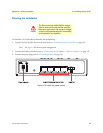
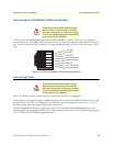
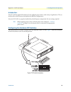
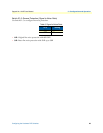
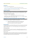
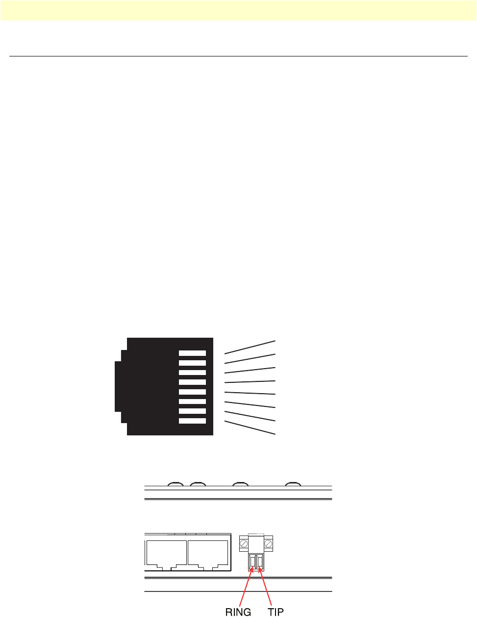
2. The CL1214E is equipped
with an RJ-45 interface jack (figure 4) or terminal block (figure 5) that can be
used on the CopperLink interface. The CopperLink inter
face is a two-wire interface. Observe the signal/
pin relationships on the CL1214E’s CopperLink interface jack.
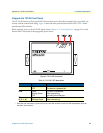
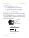
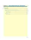
The RJ-45 connector on the CL1214E ‘s twisted pair interface is polarity insensiti
ve and is wired for a two-wire
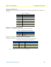
interface. The signal/pin relationship is shown in figure 4.
1 (no connection)
2 (no connection)
3 (no connection)
4 (RING)
5 (TIP)
6 (no connection)
7 (no connection)
8 (no connection)
1
2
3
4
5
6
7
8
Figure 4. CL1214E (RJ-45) twisted pair line interface
Figure 5. CL1214E (Terminal Block) twisted pair line interface