


1. Configure IP address 40
OnSite 2800 Series User Manual 3 • Getting started with the OnSite Managed VPN Router
1. Configure IP address
Power connection and default configuration
First the OnSite VPN Router must be connected to the mains power supply with the power cable. Wait until
the
Run
LED stops blinking and lights constantly. Now the OnSite VPN Router is ready.
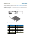
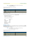
The factory default configuration for the Ethernet interface IP addresses and network masks are listed in table 9.
All Ethernet interfaces are activated upon power-up.
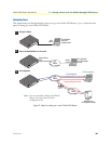
If these addresses match with those of your network, go to section “2. Connect the OnSite VPN Router to the
network” on page 42. Otherwise, refer to the following sections to change the addresses and network masks.
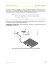
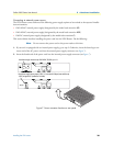
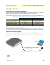
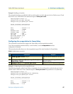
Connect with the serial interface
The Console port is wired as an EIA-561, RS-232 port. Use the included Model 16F-561 adapter and cable (see
figure 10) between the OnSite VPN Router’s Console port and a PC or workstation’s RS-232 serial interface.
Activate the terminal emulation program on the PC or workstation that supports the serial interface (e.g.
HyperTerm).
Figure 10. Connecting to the terminal
Terminal emulation program settings:
• 9600 bps
• no parity
• 8 bit
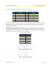
Table 9. Factory default IP address and network mask configuration
IP Address Network Mask
Interface Ethernet 0/0 (ETH0) 172.16.40.1 255.255.0.0
Interface Ethernet 0/1 (ETH1) 192.168.1.1 255.255.255.0
Interface Ethernet 0/2 (ETH2) x.x.x.x x.x.x.x
Interface Ethernet 0/3 (ETH3) x.x.x.x x.x.x.x
Interface Ethernet 0/4 (ETH4) x.x.x.x x.x.x.x
Link
100M
Activity
E
n
e
t 0
IPLink VPN Router
Run
Link
100M
Activity
E
n
e
t 1
Power
Console
Serial Terminal
Note A Patton Model 16F-561 RJ45 to DB-9 adapter is included with
each IPLink 2800 Series device